background image


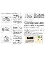
                                  NORMAL VIEW OF LCD FOLLOWING SET-UP 


LCD DISPLAY SCREEN


1                                  2                   3             4           5


                          6 


      15   

                          7                   


      16 

                           8 


      17   

                           9 


      18 


                                              10            11     12      13        14          

         On the following page, a brief description of the LCD SCREEN DISPLAY ICONS      

         is provided to understand  the many features of the AQUA SMART™ system. 


         For a more complete explanation of the OPERATING FUNCTIONS of these features,      
         review the PROGRAM OPERATION  and OPERATING FEATURES  in a later  

         sections of this  manual. (See pages 26-29).   


                                                                            20. 


LCD DISPLAY SCREEN ICONS


1.


PROGRAM FOR:  Flashes when entering programming function. Stays  
                               illuminated when programming times and temperatures.  

2.


DAY: Flashes when current day or day of week is being programmed during 

          initial set-up. Displays in normal state. 

3.


PERIOD: Displays in program mode and when programming. 

4.


SYNC: Indicates 2-way communication in between Transmitter and Receiver. 

5.


ALERT:  Indicates that 2-way communication failed. Check operation at the  

              RECEIVER with Transmitter nearby. 

6.


MODE: Indicates MODE of operation. ON-AWAY-VACATION-PROGRAM. 

7.


HEATER: Flashes when entering programming function. Stays illuminated 

when programming times and temperatures. 
       ON-OFF Icons: Display when entering program settings. Flashes when      

                                  programming the ON and OFF times and temperatures. 

8.


USB:  Reserved for future wireless feature. Not in operation on this model. 

9.


OVERRIDE: Displays when “programmed” SET TEMPERATURE is          

                     overridden. Override operates in the PROGRAM mode only. 

10.


kWh Use/MO.: Displays and stores kWh usage for a 30 day period before 

automatically resetting to “zero”. Transmitter stores 12 previous kWh readings 

11.


TIME: Displays the CURRENT time in AM-PM. 

12.


HEATING: The word HEATING and the STEAM TRAILS will begin blinking   

                   when the water heater is in the “powering” state. 

13.


BALANCING: During initial set up of system, icon begins blinking when    

                        “BALANCEING” actual water heater temperature with the   
                        Thermal Sensor reading. 

14.


SENSOR TEMP SET:  Displays temperatures in the BALANCING process  

                                      and in 5°F increments in the PROGRAMMING mode. 

15.


BATTERY: Battery power is low. Replace batteries in 2-4 weeks. 

16.


LOCK: Displays when “LOCK OUT” of Transmitter is engaged. 

17.


SENSOR TEMP: Displays the THERMAL SENSOR temperature from the  

                                HOT water pipe. 

18.


 °F°/C: Factory programmed in °F (Fahrenheit). User can change to  
  °C  (Celsius).                

TRANSMITTER  FUNCTIONS 
 

In  the  sections  that  follow,  each  ICON  and  Transmitter  function  will  be  discussed,  in 
detail, to provide a full understanding of the software logic that “commands” the AQUA 
SMART™
 system. Detailing these functions allows user to fully understand the “logic” of 

the various features in the AQUA SMART™ system. 
              Further demonstrations of these functions can be found on our  

              website/video at:  www.aquaenergysaver.com. We suggest viewing this  
              video to answer any questions about the AQUA SMART™ system. 
 

                                                                    21. 


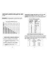
   TRANSMITTER LCD & SET-UP


Summary of Contents for 91510

Page 1: ...ic version of the AQUA SMART owner s manual translated in FRENCH can be found on our website under OWNERS MANUAL www aquaenergysaver com Une version électronique de l AQUA SMART Manuel du propriétaire traduit en français peut être trouvé sur notre site web www aquaenergysaver com INSTALLER NOTES The AQUA SMART installation is primarily an electrical installation which may be made by an individual ...

Page 2: ...ers and businesses to address the high energy use as well as the efficiency of hot water heating whether using electric natural or propane gas models The AQUA SMART system was developed as a RETROFIT SYSTEM for previously installed electric hot water heaters or newly installed electric hot water heaters that do not include factory installed energy saving features The AQUA SMART system can save 20 ...

Page 3: ...tively charged the other being negatively charged Each wire delivers electricity to the hot water heater by alternating polarities and doubling the current to the water heater The wiring to the water heater must be connected to a breaker rated at a maximum of 30 amps or meet the ampere requirements for the water heater that the AQUA SMART is to be installed on The bare copper or green ground wire ...

Page 4: ...tailed explanation of this procedure The BALANCING programming is EXTREMELY important to the proper set up of the transmitter and operation of the AQUA SMART system We recommend you proceed with the above step NOW so that the HOT water pipe will cool down before the BALANCING number is entered into the Transmitter See pages 23 24 for the BALANCING procedure Draw a small glass of HOT water from a f...

Page 5: ... ea Long Sheet Metal Screws SMS to mount Receiver base to top of water heater 3 4 ea Wire nuts to attach wires inside Receiver to Incoming Power Water Heater wires 4 1 ea Pipe clamp to affix THERMAL SENSOR to HOT water pipe Packed with Receiver 5 2 ea plastic cable ties to affix insulating foam to HOT water pipe 8 RECEIVER TOP COVER 1 4 Mounting screws attach RECEIVER COVER to RECEIVER BASE 2 LEAR...

Page 6: ... 10 5 Position the Receiver BASE over the wires coming from the water heaters junction box and attach the Receiver BASE to the top of the water heater with 4 of the SMS supplied in the hardware package 6 Using the same incoming power supply wires and connector removed in Step D SECTION 1 attach the wires connector thru the back of the Receiver BASE in the opening and reattach connector nut to the ...

Page 7: ...WIRES AND TO THE HOT WATER HEATER WIRES EACH OF THE WIRES FROM THE RECEIVER ARE LABELED TO ASSIST MAKING PROPER CONNECTIONS TO THE OF INCOMING POWER GROUND WIRES AND TO THE 2 WIRES COMING FROM THE HOT WATER HEATER IMPORTANT IMPORTANT IMPORTANT IT IS CRITICAL TO FOLLOW THESE WIRING CONNECTIONS FOR RELIABLE OPERATION OF THE AQUA SMART SYSTEM ...

Page 8: ...lamp so the THERMAL SENSOR head is covered by the rubber insulation and is snug against the HOT water pipe Following the securing of the THERMAL SENSOR head to the HOT water pipe wrap the piece of foam insulation over the CLAMP SENSOR and firmly attach with 2 wire ties BE SURE TIES ARE INSTALLED SO THEY CLICK LOCK The foam insulation was packed in the shipping box The wire ties are in the hardware...

Page 9: ...r illuminated indicating a problem at the breaker incoming power lines or with the Receiver A loss of hot water will also result Review BY PASS switch operation in previous section See page 16 SECTION 4 1 Locate the TRANSMITTER and hardware bag in carton The transmitter hardware bag will include 2 ea AAA batteries 2 ea Screw type Wall Anchors 2ea Mounting screws 1ea Thermometer strip and a paper m...

Page 10: ... not receive a confirmation signal from the Receiver within 5 seconds the WARNING icon on the Transmitter s LCD screen will illuminate on the LCD screen and the mode selection process will need to be repeated Test all 4 modes in a similar manner NOTE Upon the Receiver receiving any of the Transmitter s signals you may hear the clicking sound of a relay inside the Receiver case further confirming r...

Page 11: ...9 OVERRIDE Displays when programmed SET TEMPERATURE is overridden Override operates in the PROGRAM mode only 10 kWh Use MO Displays and stores kWh usage for a 30 day period before automatically resetting to zero Transmitter stores 12 previous kWh readings 11 TIME Displays the CURRENT time in AM PM 12 HEATING The word HEATING and the STEAM TRAILS will begin blinking when the water heater is in the ...

Page 12: ...mes and prepare to enter the required data 1 BALANCING THE THERMAL SENSOR PREVIOUS INSTRUCTIONS ON PAGE 6 RECOMMENDED THAT YOU RECORD THE WATER TEMPERATURE FROM THE THERMOMETER STRIP THIS IS THE READING THAT IS TO BE ENTERED IN THE SENSOR TEMP WINDOW ON THE TRANSMITTER S LCD A small THERMOMETER STRIP has been supplied to allow user to measure the ACTUAL temperature of the hot water coming out of a...

Page 13: ...INITIAL SET UP procedure User MUST match the WATTAGE rating of the water heater to the Receiver that the AQUA SMART has been installed on This procedure is necessary to allow the system s software to accurately calculate the kWh electrical usage when the water heater is operating On the front of the water heater jacket there will be several labels Locate the label that lists the water heater capac...

Page 14: ...en ON OFF at the end of this manual See pages 36 37 IMPORTANT NOTE The FACTORY SET program settings may not match with the user s daily activities and reprogramming by the user may be necessary User programming instructions are covered on pages 27 29 26 PROGRAM OPERATION OF THE AQUA SMART SYSTEM continued USER SET PROGRAMMING PROCEEDURES User may change the following settings but only in the PROGR...

Page 15: ... be no less than 10 F from the ON temperature setting Review the matrix protocol charts for the ON OFF temperature settings and triggering spreads between ON OFF on pages 36 37 Temperature settings between the 75 F and 120 F will operate within a 5 F temperature spread swing See page 37 Should user want to set lower temperatures user can activate the VACATION mode but will have to remember to retu...

Page 16: ...eeping sounds at the transmitter every 15 minutes alerting the returning homeowner that the system has entered the AWAY setting in the AQUA SMART MODE and the user needs to reset the Transmitter The AMBER LED on the Receiver will also be blinking 30 OPERATING FEATURES OF THE AQUA SMART SYSTEM continued KILOWATT kWh HOUR USAGE The AQUA SMART system features an ENERGY USAGE factor which uses its sof...

Page 17: ...batteries When the batteries are removed the software in the Transmitter will memorialize all settings with the exception of TIME DAY of WEEK TEMPERATURE SENSOR and KWh Use 32 LOCKOUT A lockout feature allows the user to set a LOCKOUT mode on the Transmitter only to be unlocked by the user that programmed the Transmitter Press and hold the SET and UP buttons for more than 5 seconds to activate or ...

Page 18: ... 29 of a residential electric bill reducing the amount of energy to maintain higher temperatures is recommended VACATION MODE In the VACATION MODE the water heater will operate between 40 F and 50 F thereby reducing energy consumption This setting is recommended when the homeowner will be away for 7 days or longer periods of time This is the most economical mode to engage for the greatest energy s...

Page 19: ...atures ON F OFF 120 115 110 105 100 95 90 85 80 75 120 X X X X X X X X X X 115 X X X X X X X X X X 110 OK X X X X X X X X 105 OK OK X X X X X X X X 100 OK OK OK X X X X X X X 95 OK OK OK OK X X X X X X 90 OK OK OK OK OK X X X X X 85 OK OK OK OK OK OK X X X X 80 OK OK OK OK OK OK OK X X X 75 OK OK OK OK OK OK OK OK X X UNDERSTANDING SOFTWARE MATRIX PROTOCAL WHEN USER ENTERS TEMPERATURE PROGRAMMING ...

Page 20: ...ire the removal of the Receiver cover to check the circuits If you are not familiar with testing electrical components we STRONGLY recommend that you contact a qualified electrician to conduct a further diagnosis of the Receiver Visit our website www aquaenergysaver com for further information on troubleshooting 38 SPECIFCATIONS WARRANTY FCC ID s Transmitter xxxxxxxxxxxxxx Receiver xxxxxxxxxxxxxxx...

Page 21: ...r any radio or TV interference caused by unauthorized modifications to this equipment Such modifications could void the user s authority to operate the equipment Le présent appareil est conforme aux CNR d Industrie Canada applicables aux appareils radio exempts de licence L exploitation est autorisée aux deux conditions suivantes 1 l appareil ne doit pas produire de brouillage et 2 l utilisateur d...

Reviews: