D. Disconnect the incoming power supply
lines, cable, conduit and connector
leading to the junction box on top of
the water heater.
E. There should be 2ea. –powering wires,
plus a ground coming from the power
supply. There should be 2 wires coming
out of the WATER HEATER’s junction
box
.
SECTION 2
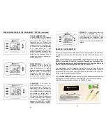
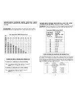
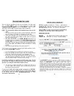
Remove the 4 screws holding the receiver cover to the base and remove cover from the
base. The receiver contains a plastic bag holding the components pictured below.
(See pg. 9)
HARDWARE PACKAGE
4
5
2
3 1
1.
1 ea. - Ground wire & Long Sheet Metal Screw (SMS) to ground water heater.
2.
4 ea. - Long Sheet Metal Screws (SMS) to mount Receiver base to top of water heater.
3.
4 ea. - Wire nuts to attach wires inside Receiver to Incoming Power & Water Heater wires.
4.
1 ea. - Pipe clamp to affix THERMAL SENSOR to HOT water pipe. (Packed with Receiver)
5.
2 ea. - plastic cable ties to affix insulating foam to HOT water pipe.
8.
RECEIVER - TOP COVER
1.
4 Mounting screws attach RECEIVER COVER to RECEIVER BASE.
2.
LEARN button to accept Transmitter’s security code upon initial set-up.
3.
Illuminating LEDs indicating the 4 MODES of operation.
RECEIVER - MOUNTING BASE
4.
Mount BASE to top of water heater with the 4 SMS provided
in the hardware package. (See mounting holes #4).
9.
INSTALLING THE RECEIVER
THIRD - DISCONNECT POWER SUPPLY WIRES FROM JUNCTION BOX COVER
1
2
3
RECEIVER
3
2
1
4
4


