background image

Aquatic 21

Millennium Owner's Manual & Installation Guide

INSTALLATION  INSTRUCTIONS

 DUAL SIDED REMOTE CONTROL INSTALLATION

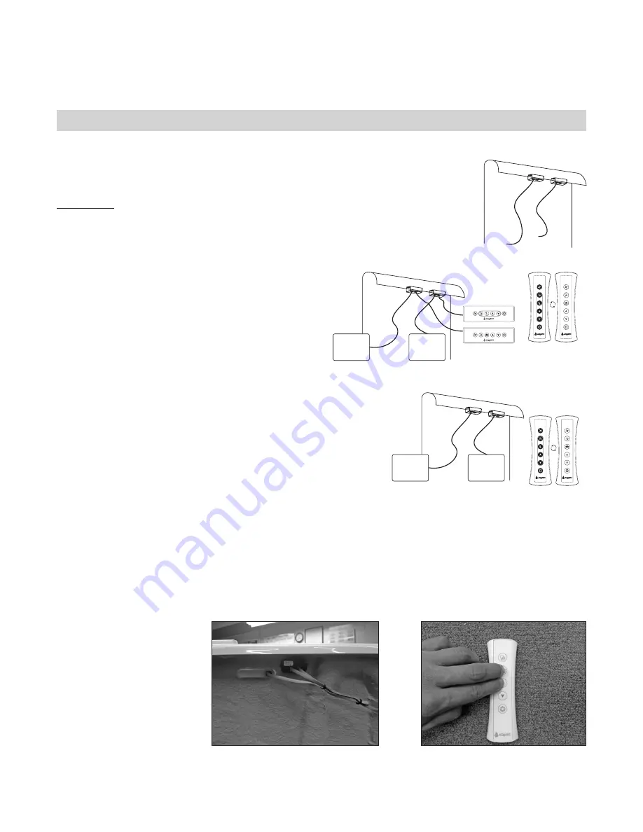
Receiver Module Installation

the Receiver Module and remote may be used in conjunction with the supplied keypad or  

without. The two receiver modules must be installed under the bathtub rim.

IMPORTANT: In order to obtain the best reception possible, we recommend not to  install  

the receiver module next to the faucets or metal piping. Location of the receiver module  

must be easily accessible from the outside of the bathtub for maintenance.

Remote control and keypad used to activate the systems

1.  Plug in the cables as shown on the drawing.

2.  Once everything is connected, the remote control  

is ready for synchronization.

Remote control only, to activate the systems

1.  Plug in the cables as shown on the drawing.

2.  Once everything is connected, the remote control is  

ready for synchronization.

Synchronization

1.  Once the system has been connected, each side of the remote control  

must be synchronized with its own receiver module.

2.  Switch off the main breaker or unplug the two systems and switch it  

on again one at a time.

3.  From this moment, you have 15 seconds to proceed with  

the synchronization.

4.  Press simultaneously on the button 2 and button 3 of the remote for 4 seconds on the side you would like to program.

5.  Keeping the first system plugged in, plug in the second system and follow steps 2 – 4.

6.  The remote control is now synchronized on both sides and ready to use. Now you should be able to control the two 

systems independently.

7.  If the synchronization is not  

successful the first time, you  

should resynchronize, starting  

from step 2.

Modules and keypads 

are factory installed

Figure 8

RECEIVER

MODULES

DUAL SIDED

REMOTE CONTROL

BLOWER OR

LECTRONIC CONTROL

BLOWER OR

ELECTRONIC CONTROL

SYSTEM 

#

1

SYSTEM #2

RECEIVER

MODULES

BLOWER OR

ELECTRONIC CONTROL

BLOWER OR

ELECTRONIC CONTROL

SYSTEM #1

SYSTEM #2

DUAL SIDED

REMOTE CONTROL

RECEIVER

MODULES

Figure 7A

Figure 7B

Summary of Contents for Millennium 10

Page 1: ...are subject to change without notice Dimensions listed in inches mm Installer This booklet must be given to the product owner Please add important information below Model ___________________________________ Purchase Date ___________________________________ Serial ___________________________________ Distributor ___________________________________ ...

Page 2: ...aterfall Spout 10 Plumbing 10 Electrical Installation 11 13 Inline Maintenance Heater Wiring and Operating Instructions 14 Final System Test Clean Up 15 OPERATION Bathside Control Systems 16 18 Jet Operations 19 20 Dual Sided Remote Control Installation 21 22 TUB CARE Maintenance 23 24 Repair 24 WATER QUALITY Chemical and Water Quality 25 26 TROUBLESHOOTING GUIDE 27 REPLACEMENT PARTS LIST 28 29 RE...

Page 3: ...rician and plumber AQUATIC Product Warranty Registration Information 8101 E Kaiser Blvd Suite 200 Anaheim CA 92808 800 945 2726 Fax 866 544 5353 www aquaticbath com IMPORTANT To activate Product Warranty please register with Aquatic Your product warranty must be registered and confirmed with Aquatic through the Serial Number on your unit To register please contact Aquatic 800 945 2726 www aquaticb...

Page 4: ...utton The GFCI should interrupt power Push the reset button Power should be restored If the GFCI fails to operate in this manner there is a ground current flowing indicating the possibility of an electric shock Do not use this unit Disconnect the unit and have the problem corrected by a qualified service representative before using To reduce the risk of injury enter and exit the bath slowly This p...

Page 5: ...unconsciousness with the possibility of drowning Never use the air whirlpool while under the influence of alcohol anticoagulants stimulants antihistamines vasoconstrictors vasodilators hypnotics narcotics or tranquilizers 7 Persons with a medical history of heart disease low or high blood pressure circulatory system problems or diabetes should consult a physician before using a air whirlpool 8 Per...

Page 6: ...s been type tested and found to comply with the limits for a class B computing device in accordance with the specifications in subpart J of part 15 of the FCC rules which are designed to provide reasonable protection against such interference in a residential installation However there is no guarantee that interference will not occur in a particular installation If this equipment does cause interf...

Page 7: ...ined in accordance with good industry practice and the specific Aquatic directions contained in the Owner s Manual and Installation Guide EXCLUSIONS These warranties do not extend to or do not cover defects caused by 1 Shipping damage by carriers or installation errors 2 Accident acts of God abuse or misuse 3 Unreasonable use including any use for non bathing purposes or failure to provide reasona...

Page 8: ...or 10 minutes With the pump running turn on the blower Check all functions Inspect the tub completely Any defect must be reported to Aquatic prior to installation in order to have it covered by warranty Should inspection indicate any damage contact Aquatic immediately 4 Check to ensure that your installation will conform to all applicable codes and secure necessary permits All electrical and plumb...

Page 9: ...below NOTE Due to the variety of installations possible framing procedures other than those described may be required Plumb in selected location using a level Level front to back and across both sides A ledge under the rim or an apron without a ledge may be constructed as required see Figures 1A 1B and 1C Where installation will be against a wall stud wall framing should allow for wall sheathing m...

Page 10: ...d has been turned off Allow water to stand in tub for at least 30 minutes before draining AQUATIC WILL NOT BE RESPONSIBLE FOR WATER DAMAGE OF ANY KIND IN CONNECTION WITH ONE OF OUR AIR WHIRLPOOL BATHS Aquatic recommends the use of 3 4 valves 3 All Millennium Series models are equipped with an integral Fast Fill Waterfall Spout unless ordered without this feature Purchasing a spout is unnecessary h...

Page 11: ...d however we do specify its use All known code authorities require a GFCI Rough in wiring to junction boxes Two 240V 4 wire 50 AMP GFCI protected circuit See electrical schematics for junction boxes on pages 12 and 13 Bonding wire Connect a 8 bare copper bonding wire from the pump motor or motors and heater to the cold water plumbing or other suitable ground Grounding is required The unit should b...

Page 12: ...ND GREEN 3 LODE RED TO CIRCUIT BREAKER PANEL JUNCTION BOX 1 PUMP CONTROL J 1 HEATER BLOWER CONTROL 3 LODE 2 NEUTRAL 1 GROUND 4 LODE 14 4 AWG 4 LODE BLACK 2 NEUTRAL WHITE 1 GROUND GREEN 3 LODE RED TO CIRCUIT BREAKER PANEL JUNCTION BOX 2 BLOWER CONTROL 240V 50AMP J 2 HEATER CIRCUIT BREAKER PANEL CIRCUIT BREAKER PANEL PUMP CONTROL BOX PUMP CONTROL UP TO 25 FEET REFER TO NEC UP TO 25 FEET REFER TO NEC...

Page 13: ... 1 BLOWER 2 SEQUENCER OUTPUT INTPUT UP HAUT W D KEYPAD AUX NEMA PLUG NEMA PLUG NEMA PLUG AMP PLUG RECEIVER MODULE 12 72 NEMA PLUG BLOWER CONTROL HEATER RED BLACK GREEN WHITE PUMP 2 NEMA PLUG RED BLACK GREEN WHITE NEMA PLUG BOX PUMP CONTROL BOX J 1 J 2 REMOTE RECEIVER MODULE REMOTE ELECTRICAL JUNCTION BOX ELECTRICAL JUNCTION BOX 50A 240VAC 50A 240VAC B1 B1 B2 B2 P1 P1 P2 P2 L L H H ELECTRICAL INSTA...

Page 14: ...ensed electrician in compliance with local and national electrical codes In addition a GFCI MUST protect all branch circuits to the whirlpool 1 Two 240V 4 wire 50 AMP GFCI protected circuit 2 Use copper conductors only 3 Insure the heater and pumps are properly GROUNDED and pump is BONDED as required CAUTION Before use of the blowers pumps and heater test the GFCI for proper operation The blowers ...

Page 15: ...ian Malfunctions of the pump blower motor whirlpool controls or the circulating system should be reported to the distributor who supplied the air whirlpool tub Clean up 1 Remove all construction residue and foreign materials Wipe unit clean with a damp rag otherwise staining may occur 2 Plaster may be removed by scraping with the edge of a piece of wood or rigid plastic DO NOT use metal scraper Fo...

Page 16: ...E When the blower is on without the sequencer press and hold to decrease the blower speed Release pressure at the desired speed When the sequencer is on press to decrease the speed at which the sequencer operates Release pressure at the desired speed ON When Pressed 6 CHROMATHERAPY 1st Press Turn on the light in white ON 2nd Press Rainbow cycle Low speed ON 3rd Press Rainbow cycle High speed ON 4t...

Page 17: ...cle Backjet row All On All Off Advanced Programming PRESETS This mode allows the user to start the tub with his preferred settings with the pres of a button Up to 4 different presets can be configured To Configure the Settings Start all desired systems Adjust the blower sequencer speed and the light color Press button 1 for more than 1 second LED s 2 3 4 and 5 will blink You have 10 seconds to cho...

Page 18: ...o maximum speed OFF 4 SPEED INCREASE 1st Press Press and hold to increase the blower speed release pressure at the desired speed When in cycles mode increases the speed at which the cycle operates ON WHEN PRESSED 5 SPEED DECREASE 1st Press Press and hold to decrease the blower speed release pressure at the desired speed When in cycles mode decreases the speed at which the cycle operates ON WHEN PR...

Page 19: ...ystem Pressure Plus Jets and Pressure Flo Hydrotherapy Jets Shiatsu Back Jetting System To adjust pressure see Figure 3A 1 Grasp the outer ring of the jet 2 Turn the jet clockwise to increase flow counter clockwise to shut off To remove jet see Figure 3B 1 Grasp the outer ring of the jet 2 Turn the jet counter clockwise until the jet clicks then pull To replace or change jet see Figure 3B 1 Insert...

Page 20: ...he hip and leg areas To adjust pressure see Figure 5A 1 Grasp the outer ring of the jet 2 Turn the jet clockwise to increase flow counter clockwise to shut off To adjust direction see Figure 5B 1 Using fingertip move jet eye to desired location To remove jet see Figure 5C 1 Grasp the outer ring of the jet 2 Turn the jet counter clockwise until the jet clicks then pull To replace or change jet see ...

Page 21: ... synchronization Synchronization 1 Once the system has been connected each side of the remote control must be synchronized with its own receiver module 2 Switch off the main breaker or unplug the two systems and switch it on again one at a time 3 From this moment you have 15 seconds to proceed with the synchronization 4 Press simultaneously on the button 2 and button 3 of the remote for 4 seconds ...

Page 22: ...sition of the magnets with a marker or pencil CAUTION Magnets always have a positive and negative side and will only be attracted to one side Consider this to avoid applying the silicone to the wrong side 3 Install magnets on back side A Apply a dab of silicone to the magnets place and maintain in the premarked position B Let dry in this position WARNING The magnets are extremely powerful despite ...

Page 23: ...amount of low foaming powder or crystal substance the whirlpool action intensifies the foaming properties of soaps The use of certain bubble baths and bath additives may increase the level of accumulations of bath residue in the whirlpool system If excess accumulations persist you should discontinue use of these products If you have followed the monthly purging instructions and still have an exces...

Page 24: ...member when contacting your dealer always have your serial number proof of purchase and model number available This will ensure a quick response on warranty items The model and serial numbers are located above the pump on the backside of the air whirlpool note all warranty repairs must be authorized by aquatic before work is started for service always contact your dealer CAUTION Care should be tak...

Page 25: ...al cleaning A chlorine containing compound is the best cleaner Avoid abrasives to limit scratching fixtures which will make them even more susceptible to bacteria 2 Chemical Quality The water supplied by individual wells or water systems always contains chemicals usually in amounts below those which the consumer would notice Examples of such chemicals which are of potential concern for the owners ...

Page 26: ... company to test your water and suggest solutions if a problem is present 3 Treatment If you have contacted your water supplier and followed their instructions and you are still having problems you need to increase the frequency of applications of low foaming detergent bleach starting from monthly purging down to using it every other day as required to eliminate your particular problem The use of ...

Page 27: ... motor bearings 2 Pumps touching a stationary object 3 Suction line partly plugged 4 Pump not supported properly 1 Contact Aquatic 2 Refer to installer dealer 3 Clean and unplug 4 Contact Aquatic Leakage of water at shaft 1 Replace pump 1 Contact Aquatic Leaking unions 1 O ring missing or damaged 2 Plumbing in a bind 3 Loose unions 1 Contact Aquatic 2 Contact Aquatic 3 Tighten unions Vibration noi...

Page 28: ...ROTxx ROTATIONAL SWIRL JET 4B 8180JTB JET BODY 4C 8180NUT JET NUT 5A 8180DIRxx DIRECTIONAL JET 5B 8180JTB JET BODY 5C 8180NUT JET NUT 6A 8182DIRxx 6B 8182JTB 6C 8182NUT 7A 8460300WH FAN JET ASSY WHITE 8460300BI FAN JET ASSY BI 8460300BK FAN JET ASSY BLACK 8460300BO FAN JET ASSY BO 8460300ST FAN JET ASSY SILVER 8102ESCBN FAN JET ASSY BRUSHED NICKEL 8102ESCBR FAN JET ASSY POLISHED BRASS 8102ESCCR FA...

Page 29: ... 750W HEATER 120V W NEMA 16A 8095HEATER 1 5 KW MAINTENENCE HEATER 16B 2PC HEATER SPLIT NUT 16C 8515FTG 2 X 1 5 ADAPTER PUMP UNION 16D 8108MOTOR 1 75HP 120V PUMP 16E GASKET O RING 16F 1 5 X 1 TAILPIECE 17A 8454CONTROL CONDO SPA CONTROL BOX 18A 8452CONTROL MILLENNIUM EVO2 CONTROL BOX 18B AIR SEQUENCER COMMUNICATION CABLE 19A 8108MOTOR 1 75HP 120V PUMP 19B 8515FTG 2 X 1 5 ADAPTER PUMP UNION 19C 8150U...

Page 30: ...30 Aquatic Millennium Owner s Manual Installation Guide REPLACEMENT PARTS MAP 1a 1c 1d 2a 2b 3a 3a 3b 3c 4a 4b 4c 6a 6b 6c 5a 5b 5c 8a 8b 8c 7a 7b 7c 7d 1b 9 10 ...

Page 31: ...Aquatic 31 Millennium Owner s Manual Installation Guide REPLACEMENT PARTS MAP 11a 11b 12 13a 13b ...

Page 32: ...32 Aquatic Millennium Owner s Manual Installation Guide REPLACEMENT PARTS MAP 14a 14b 14c 14d 14e 14f ...

Page 33: ...Aquatic 33 Millennium Owner s Manual Installation Guide REPLACEMENT PARTS MAP 21b 21c 21a 21d 16a 16b 16c 16d 16f 16e 17a 18a 18b 20b 20c 20a 15a 15b 15c 19a 19b 19c ...

Page 34: ......

Page 35: ......

Page 36: ...Revision 007 5 06 AQUATIC Fax On Demand System Toll Free 877 618 7024 8101 E Kaiser Blvd Suite 200 Anaheim CA 92808 800 945 2726 Fax 866 544 5353 www aquaticbath com 8MANMIL F O D 9000 Rev 3 14 ...

Reviews: