background image

20 Aquatic

Serenity Owner's Manual & Installation Guide

INSTALLATION  INSTRUCTIONS

FREESTANDING MODELS

Serenity 11 & 13 Installation

Before the floor installation is complete, make sure the floor is level. Once the floor installation  

is complete, determine the exact location of the bath and trace the contour of the  

bath with an erasable marker pen. 

NOTE: 

You will need to remove the  

wooden base attached to the bottom of the unit for shipping.
For information on electrical installation, maintenance and care,  

troubleshooting and warranty, please refer to the Table of Contents.

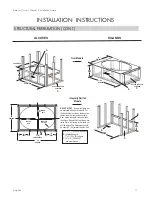
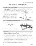
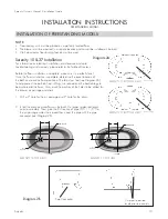
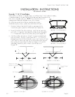
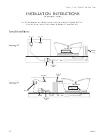
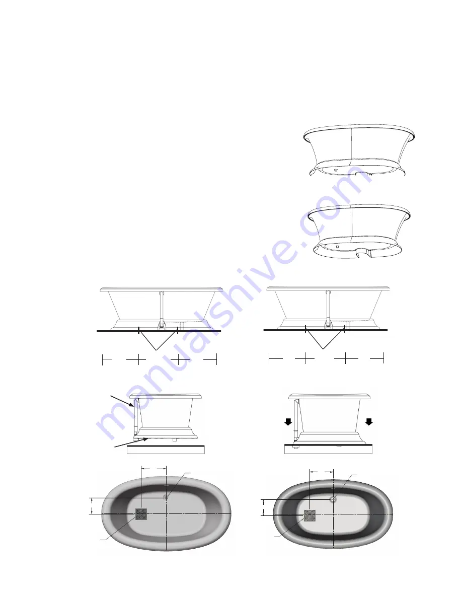
1.  Determine the exact location of the drain, air passage and the  

two anchoring points at each end of the bath (see Diagram 3A).

2.  To prevent the bath from moving sideways, secure the two anchoring  

pins (3/8” x 3” lag bolts, not supplied) to the floor. Leave the lag bolts  

1 1/2” above floor. Wipe off the marker tracings (see Diagram 3B).

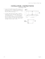
3.  Install the overflow and drain on the bath. Cut pipes to desired length  

prior to assembly.  Glue the first pipe section (PVC 1 1/2”) of the air  

passage to go under the floor and make sure pins are lined up with holes  

in tub. Apply a silicone seal under the rim of the base and lay the bath  

down putting the pipes through the floor (see Diagrams 3C and 3D).  

Immediately remove any excess silicone. Also see Top Views  

Diagram 3E.

3E

SERENITY 11 BOTTOM VIEW

SERENITY 13 BOTTOM VIEW

3A


 14" 

 9" 

TOP VIEW

6" x 6"

BOX OUT

DRAIN HOLE

SERENITY 11 TOP VIEW

 13" 

 9" 

TOP VIEW

6" x 6"

BOX OUT

DRAIN HOLE

SERENITY 13 TOP VIEW

Cut pipes to desired

length prior to assembly

3D

3C 

100% Silicone

20”

Pipes go through  

the floor

Anchor Pins

SERENITY 11 SIDE VIEW

3B

20”

20 1/2”

Anchor Pins

SERENITY 13 SIDE VIEW

20”

20”

17”

Summary of Contents for SERENITY W9AIR7444

Page 1: ...ications are 3 8 and are subject to change without notice Dimensions listed in inches mm Installer This booklet must be given to the product owner Please add important information below Model ________...

Page 2: ...n Freestanding 18 Installation of Freestanding Models 19 22 Variable Speed Air Blower Remote Mounting Freestanding 23 24 Serenity 27 Installation 25 26 Remote Control Non Freestanding 27 28 Remote Con...

Page 3: ...formed ONLY by a qualified electrician and plumber AQUATIC Product Warranty Registration Information 8101 E Kaiser Blvd Suite 200 Anaheim CA 92808 800 945 2726 Fax 866 544 5353 www aquaticbath com IMP...

Page 4: ...ton The GFCI should interrupt power Push the reset button Power should be restored If the GFCI fails to operate in this manner there is a ground current flowing indicating the possibility of an electr...

Page 5: ...athing DONT S DO NOT operate the air bath system if The bathtub isn t filled to required levels above air channels You re pregnant until you ve consulted your doctor You re taking medications or drugs...

Page 6: ...sted and found to comply with the limits for a class B computing device in accordance with the specifications in subpart J of part 15 of the FCC rules which are designed to provide reasonable protecti...

Page 7: ...sary maintenance as specified in Aquatic Owner s Manual and Installation Guide supplied with the Air Bath 4 Any alteration customization or modification of the Air Bath or its components LIMITATIONS 1...

Page 8: ...3 Plug in blower control box and run blower for 10 minutes 4 Inspect the tub completely Any defect must be reported to Aquatic prior to installation in order to have it covered by warranty Should ins...

Page 9: ...rflow leakage is not included in the warranty of this product 3 Tub must rest entirely on its base DO NOT SUPPORT THE BASE OF THE TUB BY THE RIM Aquatic strongly recommends preparing a bed of wet mort...

Page 10: ...els 100 Silicone Sealant Tile Tile 100 Silicone Sealant 1 x 3 Ledger Tile Bed Tile Bed Wood Shim Wood Shim Wall Stud Wall Stud Tile Tub Tub Tub B A A ACCESS PANEL ON PUMP END C ACCESS PANEL ON PUMP EN...

Page 11: ...er template will be enclosed with all oval models For the deck cutout scribe on the deck two center lines a major and minor axis Next match the center lines and trace the ellipse Repeat this step thre...

Page 12: ...old valves see image at right CAUTION Do not overtighten Do not use Teflon Tape PLUMBING 1 After securing tub in place normal waste and overflow water spout and valves are installed per normal plumbin...

Page 13: ...ectric shock Do not alter the factory installed wiring A licensed electrician must provide the dedicated electrical service protected by a GFCI The location of the GFCI must be accessible for regular...

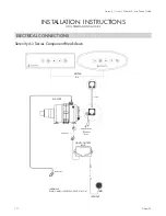
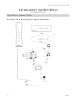
Page 14: ...UCTIONS NON FREESTANDING MODELS ELECTRICAL CONNECTIONS Serenity Air Series Component Breakdown OUTPUT INTPUT UP HAUT W D KEYPAD AUX CABLE NEMA PLUG BLOWER KEYPAD LED LIGHT LIGHT CONTROL BOX WATER DETE...

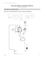
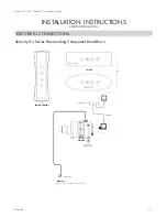
Page 15: ...NG MODELS ELECTRICAL CONNECTIONS Serenity Air Series Remote Blower Option Component Breakdown OUTPUT INTPUT UP HAUT W D KEYPAD AUX CABLE 25 CABLE 25 EXTENSION 25 NEMA PLUG BLOWER LED LIGHT LIGHT CONTR...

Page 16: ...NDING MODELS ELECTRICAL CONNECTIONS Serenity Air Series Remote Option Component Breakdown RECEIVER MODULE OUTPUT INTPUT UP HAUT W D KEYPAD AUX NEMA PLUG BLOWER LED LIGHT LIGHT CONTROL BOX WATER DETECT...

Page 17: ...EYPAD CABLE 25 NEMA PLUG REMOTE CONTROL B IMPORTANT ONE 15 AMP 120 VOLTS CIRCUIT CLASS A NOT TO BE USED WITH THIS OPTION OR RECEIVER MODULE INSTALLATION INSTRUCTIONS FREESTANDING MODELS ELECTRICAL CON...

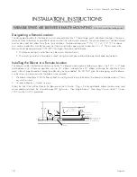
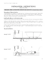
Page 18: ...r local code requirements Installing the Blower in a Remote Location The blower can be installed horizontally or vertically The blower intake maybe installed up or down Use PVC 1 1 2 pipe and adapters...

Page 19: ...four claw feet see Diagram 2A To help prevent the bathtub from shifting we recommend the bathtub legs to be anchored to the floor Also mark the position of the holes to be drilled for the blower air...

Page 20: ...secure the two anchoring pins 3 8 x 3 lag bolts not supplied to the floor Leave the lag bolts 1 1 2 above floor Wipe off the marker tracings see Diagram 3B 3 Install the overflow and drain on the bath...

Page 21: ...r pen For information on electrical installation maintenance and care troubleshooting and warranty please refer to the Table of Contents 1 Determine the exact location of the drain air passage and the...

Page 22: ...ff the marker tracings 3 Install the overflow and drain on the bath Cut pipes to desired length prior to assembly see Diagram 4B Glue the first pipe section PVC 1 1 2 of the air passage to go under th...

Page 23: ...be accessible at all times Installing the Blower in a Remote Location The blower will come attached to the one way check valve make sure the arrow on the valve is pointing away from the blower The bl...

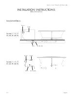
Page 24: ...stallation Guide INSTALLATION INSTRUCTIONS FREESTANDING MODELS Key Pad Receiver Blower Flow One Way Valve Key Pad Receiver Blower Flow One Way Valve Serenity 11 13 17 23 24 25 and 26 Serenity 11 13 17...

Page 25: ...and lay the bath down putting the pipes through the floor Immediately remove any excess silicone 2 Find a location for the Hartford Loop you can mount the Hartford Loop inside a wall or on a wall in a...

Page 26: ...ee directions anchored to a 2x4 Install so that two inches of loop is above the bottom of the overflow hole Key Pad Receiver Blower One Way Valve 2 Overflow Hole Hartford Loop Flow One Way Valve is Un...

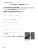
Page 27: ...Activate the System 1 Plug in the cable as shown in Figure 7B 2 Once everything is connected the remote control is ready for synchronization Synchronization 1 Once the system has been connected the re...

Page 28: ...place C Mark the position of the magnets with a marker or pencil CAUTION Magnets always have a positive and negative side and will only be attracted to one side Consider this to avoid applying the si...

Page 29: ...mote Control Only to Activate the System 1 Plug the 25 cable into the blower 2 Install the receiver module 6 10 from point of use 3 Once everything is connected the remote control is ready for synchro...

Page 30: ...consult a licensed electrician Malfunctions of the air bath controls or the circulating system should be reported to the distributor who supplied the tub Clean up 1 Remove all construction residue an...

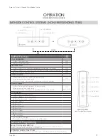
Page 31: ...en in cycles mode increases the speed at which the cycle operates ON WHEN PRESSED 4 SPEED DECREASE 1st Press Press and hold to decrease the blower speed release pressure at the desired speed When in c...

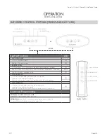
Page 32: ...raight back to maximum BLINK 3rd Press Returns to maximum speed OFF 3 SPEED INCREASE 1st Press Press and hold to increase the blower speed release pressure at the desired speed When in cycles mode inc...

Page 33: ...of the fixture using ONLY the proper tool provided for that purpose Do not attempt to remove the lens without the provided tool 4 Replace your LED light replacement LED lights can be obtained from Aq...

Page 34: ...REMOVAL Minor scratches may be removed by polishing your tub with a non abrasive car polish followed by buffing Deeper scratches can be removed by Sanding with wet 400 grit sandpaper Sanding with wet...

Page 35: ...minutes to mix cleaner with water Shut blower down and allow cleaner to soak in the bath for approximately two hours Turn on air bath and run for approximately five minutes Turn air bath unit off and...

Page 36: ...bacteria causing the problem would require lengthy and costly laboratory testing however most experts believe the bacteria responsible is Serratia marcescens These bacteria thrive on moisture dust and...

Page 37: ...soluble form that is especially noticeable with white tubs If high manganese in the water is present you may also notice black stains on white laundry If this occurs you need to contact the water supp...

Page 38: ...shut off 1 Defective control panel 2 Defective blower 1 Refer to installer dealer Replace control panel 2 Refer to installer dealer Replace control box Air Bath does not function properly while in th...

Page 39: ...Aquatic 39 Serenity Owner s Manual Installation Guide REPLACEMENT PARTS MAP 3d 11 4a 4b 3b 3c 3a Option 2a 1b 1c 1a 1d 5a 6a 6b Option 2b 2c 2d...

Page 40: ...AQUATIC Fax On Demand System Toll Free 877 618 7024 8101 E Kaiser Blvd Suite 200 Anaheim CA 92808 800 945 2726 Fax 866 544 5353 www aquaticbath com 8MANSER F O D 9005 Rev 04 14...

Page 41: ...e Dimensions listed in inches mm Installer This booklet must be given to the product owner Please add important information below Model ___________________________________ Purchase Date ______________...

Page 42: ...stallation Procedures 8 Structural Preparation 9 10 Plumbing 10 Electrical Connections 11 13 Final System Test Clean Up 14 OPERATION INSTRUCTIONS HotSoak Operations 15 Bath side On Off Controls 15 Ins...

Page 43: ...arranty If you have any questions concerning installation operation maintenance or any other aspect of your Aquatic bath please contact AQUATIC CUSTOMER SERVICE CENTER 800 945 2726 The Troubleshooting...

Page 44: ...utton The GFCI should interrupt power Push the reset button Power should be restored If the GFCI fails to operate in this manner there is a ground current flowing indicating the possibility of an elec...

Page 45: ...lead to unconsciousness with the possibility of drowning Never use the bath while under the influence of alcohol anticoagulants stimulants antihistamines vasoconstrictors vasodilators hypnotics narcot...

Page 46: ...e with the specifications in subpart J of part 15 of the FCC rules which are designed to provide reasonable protection against such interference in a residential installation However there is no guara...

Page 47: ...tSoak is subject to damage during shipping by carriers faulty installation maintenance abuse accident or other damages 2 The HotSoak is installed outdoors 3 The HotSoak is not installed in accordance...

Page 48: ...e tub completely Any defect must be reported to Aquatic prior to installation in order to have it covered by warranty Should inspection indicate any damage or leaks do not install the bath Damage or l...

Page 49: ...oduct WARNING Factory skirts do not allow for blocking up of the tub base All blocking must be solid and provide uniform support to the tub base 3 Tub must rest entirely on the base DO NOT SUPPORT THE...

Page 50: ...nd bead of silicone between the first course of tile and the bath deck PLUMBING 1 After securing tub in place normal waste and overflow water spout and valves are installed per normal plumbing procedu...

Page 51: ...require a GFCI BONDING WIRE Connect a 8 bare copper bonding wire from the pump motor heater to the cold water plumbing or other suitable ground Grounding is required For built in and custom units ins...

Page 52: ...20V SINGLE POLE BREAKER WITH GROUND FAULT CIRCUIT INTERRUPTER CLASS A ONE 20 AMP 120 VOLT CIRCUIT NEMA PLUG PUMP CONTROL BOX KEYPAD OUTPUT INTPUT UP HAUT W D KEYPAD AUX PUMP NEMA PLUG ON OFF PUMP BUTT...

Page 53: ...herapy LED MAIN BREAKER PANEL 120V 240V 60Hz NEMA PLUG LIGHT CONTROL BOX PUMP CONTROL BOX NEMA PLUG KEYPAD OUTPUT INTPUT UP HAUT W D KEYPAD AUX B OUTPUT INTPUT UP HAUT W D KEYPAD AUX C LED LIGHT NEMA...

Page 54: ...ensed electrician Malfunctions of the pump motor heater electronic controls or the circulating system should be reported to the distributor who supplied the bathtub Clean up 1 Remove all construction...

Page 55: ...d WARNING Prolonged Immersions in Hot Water May Induce Hyperthermia Hyperthermia occurs when the internal temperature of the body reaches a level several degrees above the normal body temperature of 9...

Page 56: ...TALLATION OF ELECTRONIC ON OFF TIMER CONTROL 1 Plug the On Off Timer Control into a dedicated 120 volt minimum 20 Amp outlet Speed Timer Box 2 Wait 10 20 seconds for self calibration before you depres...

Page 57: ...s can be obtained from Aquatic NOTE Do not twist LED light into socket Use gentle pressure and push LED light into place OPERATION INSTRUCTIONS KeyPad Functions 1 On Off Pump 1st Press The pump starts...

Page 58: ...facturer with the product Repeated use may be necessary SUPER SYSTEMS CLEAN PLUS does not replace the necessity to purge your HotSoak system at least twice a month with a low foaming detergent and ble...

Page 59: ...ly distributed in soil food and also in animals The best solution to keep these surfaces free from the bacterial film is continual cleaning A chlorine containing compound is the best cleaner Avoid abr...

Page 60: ...water and follow their suggestions for treatment If you are on an individual well you need to contact a water treatment company to test your water and suggest solutions if a problem is present 3 Trea...

Page 61: ...rotector trips 1 Low voltage 2 Inadequate ventilation 3 Wiring too small 1 Contact your electrician 2 Refer to installer dealer 3 Contact your electrician Pump delivers no water 1 Leakage of air into...

Page 62: ...STATE HOTSOAK 3A 8501CONTROL CONTROL BOX TMS W P ON OFF 4A OPTION 8500PAD KEYPAD KIT TMS TIMER LIGHT 5A OPTION 8500CONTROL CONTROL BOX CHROMATHERAPY 120V 5B OPTION 8020LIGHTS CHROMATHERAPY 20LEDS BULB...

Page 63: ...Aquatic 23 Serenity HotSoak Owner s Manual Installation Guide 4a 5a Option 5b 5c Option 5d Option 2a 1a 1b 1c REPLACEMENT PARTS MAP 3a 6a...

Page 64: ...Fax On Demand System Toll Free 877 618 7024 8101 E Kaiser Blvd Suite 200 Anaheim CA 92808 800 945 2726 Fax 866 544 5353 www aquaticbath com 8MANHSK F O D 9004 REV 04 14...

Page 65: ...3rd Press Returns to maximum speed 5 ON OFF LIGHT 1st Press Light ON WHITE 2nd Press Light OFF Turn OFF and ON within 3 seconds the light will change to SLOW RAINBOW CYCLE FAST RAINBOW CYCLE TURQUOIS...

Reviews: