12
AT-MGS-402 User Manual
There are (3) form C relay contacts rated 10A at 240VAC and (2) Analog Outputs
(4-20ma, 1-5V, 2-10V)
. In
addition there is (1) Remote Silence input to interface with a momentary push button that may be in a
different location than the AT-MGS-402. See items 1
(Analog outputs)
, 7-9
(Form C Relays
) and 4
(Remote Silence)
in “Figure 2-3 - AT-MGS-402 Layout” on page 7.
The additional outputs should be wired in the same manner as the power and Modbus connections. Use
appropriate conductor sizes on the form C relays that adhere to local building codes. The remote silence
and analog outputs can be wired using Belden 3106A or equivalent cable.
NOTE:
The relay contacts are rated 10A at 250VAC resistive load.
3.8 Reinstalling AT-MGS-402 Lid
WARNING:
DO NOT leave excess cable inside the gas detector housing. Failure to comply may
result in damage to the product.
CAUTION:
When installing the sensor ribbon cable, care must be taken to ensure the proper
orientation of the connector at both ends of the cable. Failure to ensure proper orientation may
result in loss of functionality and/or product damage.
NOTE:
To achieve proper seal, the lid screws should be torqued to 15 to 20 lbf in
(1.5 to 2.0 Nm.)
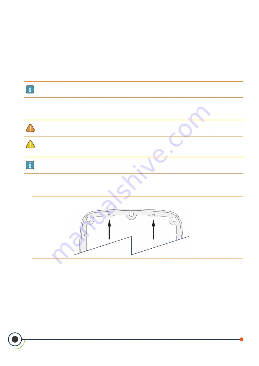
Reinstall the rubber gasket. Ensure that it is correctly seated by placing the side with two grooves face down
and the edge with two bumps on the top.
Figure 3-4 -
Rubber Gasket


