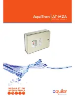
AT-MZA
Multi Zone Alarm
LEAK DETECTION SOLUTIONS
Weights & Measures House, 20 Barttelot Road,
Horsham, West Sussex RH12 1DQ
+44 (0) 1403 216100
info@aquilar.co.uk
www.aquilar.co.uk
REASSEMBLE THE MODULE
Note: Before replacing the motherboard,
ensure that the interior of
the enclosure is clean.
• Replace the motherboard and secure it in
place with the Phillips (cross-head) screws.
• Reconnect the ribbon cable (taking care not
to bend any pins in the connection).
• Close and secure the door of the enclosure.
4
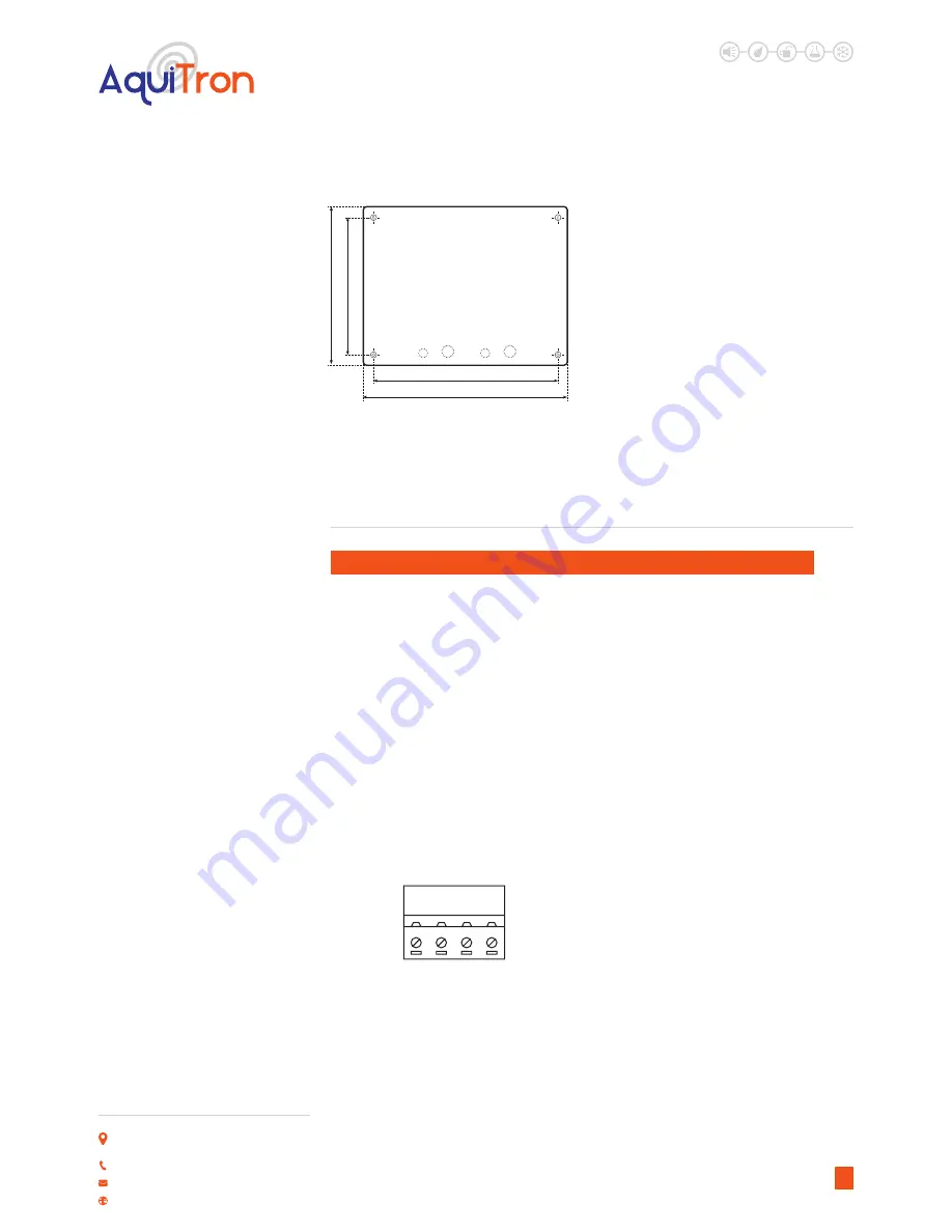
190m m
240m m
210m
m
165m
m
Figure 3
Cable entry knockouts are provided as
follows:
Back plate 4 x 20mm and 3 x 3/4”
Base of endourse 6 x 20mm and 5 x 3/4”
D. PREPARE SENSING CABLE / SENSING PROBE / DEVICE
Ensure that the sensing cable (sensing device) has been installed in accordance with the
instructions provided.
MAKE CONNECTIONS
•
Confirm that the power to the MZA unit has
been turned off.
• Open the enclosure door.
• Feed the end of the TraceTek modular
leader cable (or bulk jumper cable) through
the knockout/adapter/bushing if fitted.
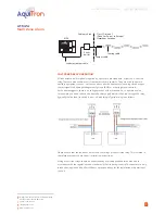
• Connect the four colour-coded wires to the
Sensor Interface plug, X3, X7, X10 and X12
(see Fig 4).
SENSOR
RED
GR
N
YEL
BLK
x3
x7
x10
x12
• Select a spare connector between zones 1
to 8.
• Zones 1-2 do not require the insertion of a
zone expansion card, MZA-EXP.
• Three cards can be added to the base unit,
giving a total of 8 individual zones. Provided
the relevant zone expansion card has been
• the relevant zone expansion card has been
inserted, you can select any sequence for
connecting the sensing cable or sensing
devise.
Important:
Observe the colour coding.
If wires are not connected to the correct
terminals, the leak detection system cannot
operate properly.
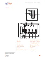
Insert the sensing cable (SI) plug into the SI
socket (item 15, 17, 19, 21 on the product
illustration on the first page).
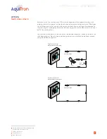
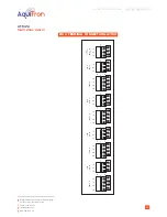
ISOLATE SPARE SENSING ZONES
Each spare sensing zone circuit or the second
zone in any of the two zone blocks, where
an expansion card is fitted, that is not to
be used must be terminated with loops of
cable between red-green and yellow-black.
(See figure 5). This will prevent the system
identifying this zone as having a cable break.
However, should there be a requirement for
all three-expansion cards to be installed, but
not used, then these must be terminated in a
similar fashion.
Figure 3
Figure 4

