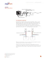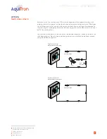
SENSOR
RED
GRN
YEL
BLK
x3
x7
x10
x12
Figure 7
AT-MZA
Multi Zone Alarm
LEAK DETECTION SOLUTIONS
Weights & Measures House, 20 Barttelot Road,
Horsham, West Sussex RH12 1DQ
+44 (0) 1403 216100
info@aquilar.co.uk
www.aquilar.co.uk
5
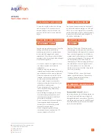
CONNECTING THE POWER WIRING
• Open door of MZA enclosure.
• Pass the power cable through the knock-
out/adapter/bushing if fitted.
• Note:
Proper grounding/earthing is
important to avoid the possibility of
electromagnetic interference.
• Connect the power supply wires to the
special three-pin terminal block marked LNE
(Live, Neutral, Earth), observing the polarity.
E. CONNECTING THE POWER CABLE AND RELAYS
x15
Figure 4
L
N
• The electrical supply should be fused
at no more than 3 amps via an un-
switched fused spur adjacent to the
unit.
• Note:
Do not exceed maximum
voltage.
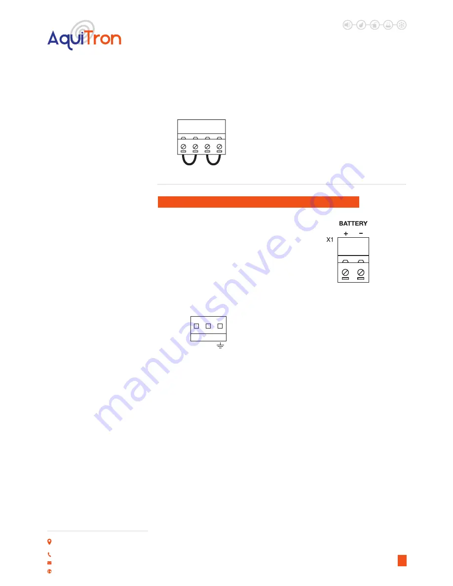
• The unit is equipped with a 12Vdc battery
back-up power circuit. If this option is
required connect the + and - (positive and
negative) battery leads (leads not supplied)
(fig 7).
BATTERY BACKUP
Figure 5
• A separate battery unit is available
AT-BU which will house a 12Vdc 7Ah
battery - AT-BAT.
• Batteries should be tested, maintained
and replaced in accordance with the
battery manufacturers instructions
and recommendations.
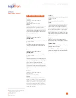
COCONNECT THE LEAK AND FAULT
(CABLE BREAK) RELAYS
The MZA has:
One LEAK relay per zone
One common LEAK relay
One summary FAULT relay
RELAY IDENTIFICATION
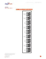
LEAK relays:
Zones1&2,X13-Z1bottom,Z2top
Zones3&4,X11-Z3bottom,Z4top
Zones5&6,X8-Z5bottom,Z6top
Zone7&8,X5 -Z7bottom,Z8top
Note:
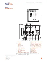
See figure 8 (at the back of this
document) for a complete figure layout.
Figure 5
Figure 6
Figure 7

