AT-MZA
Multi Zone Alarm
LEAK DETECTION SOLUTIONS
Weights & Measures House, 20 Barttelot Road,
Horsham, West Sussex RH12 1DQ
+44 (0) 1403 216100
info@aquilar.co.uk
www.aquilar.co.uk
G. TEST PROCEDURE
1. After connections are complete supply
power to the unit. If the sensing circuit
is complete and free of leaks or other
problems, the green Monitoring LED only
will illuminate.
2. Leak Simulation: For systems using TT1000,
TT3000 sensor cable or a detection probe,
use a TraceTek Mapping Tool or a small
container of water to simulate a leak. After
the time delay has expired (maximum 15
seconds) look for the following indications:
Red LEAK LED on
Green POWER LED on
LEAK RELAY in ALARM condition
(
Note:
This may cause equipment shut
down if devices are connected to the LEAK
relay contacts)
Remove simulated leak
Red LEAK LED goes out
For TT5000 and TT5001 systems, simulate a
leak condition by tightly bending and holding
the sensor cable.
3. Cable Break Simulation: For any sensor
system, disconnect any one wire at the
sensor cable terminal block or disconnect
any connector in the system. Look for the
following indications:
Yellow CABLE BREAK LED on
FAULT RELAY in ALARM condition
Restoring the connection should cause the
MZA to return to the normal indications for
that zone.
1. Complete a system inspection in the
presence of the owner.
2. Ensure a plan showing the location of the
sensor is available.
3. Check that the following information
is clearly visible adjacent to the alarm
module:
• In case of alarm instruction.
• Location of the system map in case it
is not installed adjacent to the alarm
module.
• Name and contact number of the person
responsible for operating the system.
• Supplier’s contact name and address.
4. Hand over these Installation, Operating
and Maintenance Instructions.
5. Make the owner aware that it is strongly
recommended to perform a systems
check at regular intervals, at least every six
months.
H. FINAL CHECK LIST
8
COMMISSIONING
Your system should be commissioned
by an authorised AquiTron™ or TraceTek
representative. The system map is a crucial
part of the system and should be located
adjacent to the unit and within the O&M
documents.
Important:
Store hardware and
documentation supplied with the MZA in a
secure place for later use (commissioning,
connecting interfaces, operating).
I. INVESTIGATING LEAKS AND FAULTS
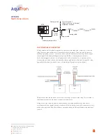
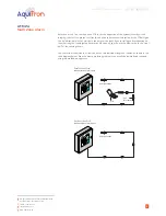
If the location of a leak is not apparent, it is often useful to subdivide the leak detection
circuit, as illustrated below. To accomplish this, it is recommend have a TraceTek Portable
Test Box (PTB) and an extra Modular End Termination is used. Contact your local TraceTek
representative to obtain these products. Note that the PTB comes with instructions on how to
use it.
To segment the system (one individual zone) and isolate problems, find a TraceTek sensing
cable or jumper cable connection at a convenient point somewhere at the center of the

