background image

INSTALLATION 


Page 6 

DRAIN


We recommend the use of a stand pipe with air trap.  


To prevent backflow from the drainage system into the 

water  softener,  always  make  sure  to  have  an  air  gap 
between the end of the drain line and the drainage system 
itself; as a rule of thumb, the air gap should be minimum 
2x the diameter of the drain line. 


Always  use  separate  drain  lines  for  the  control  valve 

(evacuation  of  rinse  water)  and  the  softener  cabinet's 
overflow. 


Lay-out  the  drain  hoses  in  such  a  way  that  pressure 

loss is minimized; avoid kinks and unnecessary elevations. 

 
1.


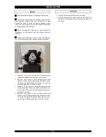
Connect a 13 mm hose to the drain connection of the 
control valve (

); secure it by means of a clamp. 

2.


Run  the  drain  hose  to  the  drainage  system  and 
connect it to the stand pipe assuring sufficient air gap. 
This  drain line  operates  under  pressure,  so  it  may  be 
installed higher than the water softener. 

3.


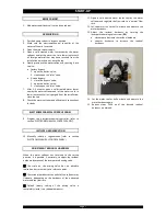
Connect a 13 mm hose to the overflow elbow, located 
at the back side of the water softener (Micro-4) or at 
the left side of the water softener (Micro-6); secure it 
by means of a clamp. 

4.


Run  the  drain  hose  to  the  drainage  system  and 
connect it to the stand pipe assuring sufficient air gap. 
This drain line does NOT operate under pressure, so it 
may NOT be installed higher than the water softener. 

ELECTRICAL 

 
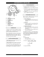
1.


Plug the transformer into an electrical outlet. 

2.


Plug  the  transformers  output  lead  into  the  socket  on 
the water softeners power cord; secure it by means of 
the clamp. 


Summary of Contents for Micro Budget

Page 1: ...2012 Aquion Inc OM EN MicroBudget Rev2012 03 O OW WN NE ER R S S M MA AN NU UA AL L Micro Budget WATER SOFTENER SYSTEM...

Page 2: ...CORD Serial Number ______________________________________________ Model _______________________________________________________ Water Hardness inlet ______________________________________ Water Hardne...

Page 3: ...hould only be undertaken by a competent person aware of the local codes in force All plumbing and electrical connections must be done in accordance with local codes Before setting up the water softene...

Page 4: ...oiler house or freezing temperatures can occur the water softener cannot be exposed to outdoor elements such as direct sunlight or atmospheric precipitation do not install the water softener too close...

Page 5: ...on treated water 1 Screw the elbow connections onto the control valve the long elbow onto the inlet port the short elbow onto the outlet port make sure to install the gasket seals Tighten the nuts fir...

Page 6: ...ontrol valve secure it by means of a clamp 2 Run the drain hose to the drainage system and connect it to the stand pipe assuring sufficient air gap This drain line operates under pressure so it may be...

Page 7: ...nical controller refer to section ELECTROMECHANICAL CONTROL PANEL INITIATE A REGENERATION 10 Manually initiate a regeneration refer to section ELECTROMECHANICAL CONTROL PANEL ADJUSTMENT RESIDUAL HARDN...

Page 8: ...1 Push in the skipper tab E that is aligned with the day indicator C 2 Turn the timer knob K counter clockwise until the time of day in the time of day window L equals the time of regeneration in the...

Page 9: ...e person Turn the timer knob K counter clockwise until the regeneration cams I are accessible loosen the locking screw H rotate the upper cam clockwise to extend the cycle time max 60 min do NOT rotat...

Page 10: ...s OPEN outlet valve from water softener is OPEN BYPASS POSITION inlet valve to water softener is CLOSED outlet valve from water softener is CLOSED MAINTENANCE POSITION inlet valve to water softener is...

Page 11: ...tool carefully push the salt to break it apart 3 pour warm water over the top of the salt to dissolve it BRINE CABINET To retain the appearance of the water softener simply wipe it with a damp cloth o...

Page 12: ...sive water in brine cabinet Refer to problem Excessive water in brine cabinet Water softener regenerates too frequently Verify regeneration frequency Excessive water in brine cabinet Improper setting...

Page 13: ...e restrictor Clean injector and or brine restrictor Plugged injector filter Clean injector filter Restricted drain line Verify drain line for kinks or restrictions Restricted brine line Verify brine l...

Page 14: ...sage per regeneration kg 0 5 0 8 Exchange capacity per kg salt m x f 41 Exchange capacity per kg salt m x d 23 Recommended maximum service flow m hr 0 4 0 6 Rinse water usage per regeneration 3 bars L...

Page 15: ......

Page 16: ......

Reviews: