Model 2500A225C
Rev A
9
2.4 INPUTS AND OUTPUTS
The input and output connectors described in the following sections are located on the unit’s front or rear panels;
refer to the Front and Rear Panel features drawings (Figure 2-1, Figure 2-2).
2.4.1
RF Input
This Type N connector is the RF input to the amplifier. It should be connected to a RF signal generator or
sweep generator.
2.4.2
RF Output
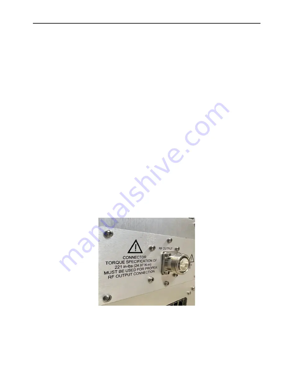
The use of proper mating, tightening and de-mating techniques, will ensure a proper connection for RF
measurement, prevent damage to the amplifier’s external connector and supporting equipment, and will
minimize the torque applied to the front panel connectors. Excessive torque cannot only damage the front panel
connectors of the analyzer but may also damage the mating connector, resulting in poor RF performance and
inaccurate measurements.
2.4.2.1
Inspection and Cleaning
When the connector threads are clean and free from defect, the coupling nuts should move freely. Inspect the
connector for defects such as:
•
Dirt, dust, metal particles and oil.
•
Damaged threads (distorted, dented, or crushed)
•
Deep scratches showing un-plated metal
•
Dents or raised edges on the mating plane.
Figure 2-3. Rear Panel 7-16 DIN Connector
Summary of Contents for 0053007
Page 2: ......
Page 4: ......
Page 6: ......
Page 18: ...Model 2500A225C iv ...
Page 28: ......
Page 70: ...Model 2500A225C 46 Rev A ...
Page 80: ...Model 2500A225C 56 Rev A Figure 4 7 SMA Module Input Figure 4 8 Final Module RF Output ...
Page 82: ...Model 2500A225C 58 Rev A ...
Page 84: ...Model 2500A225C 60 Rev A ...
Page 86: ......


