Model 500T8G18
10
Rev B
3.2.2
Mounting and Removing
The TWTA may be operated as a standalone benchtop unit, or it may be installed in a 19" rack.
When the amplifier is rack-mounted, it is strongly recommended that the supertube module be mounted above
the power supply/control module, so that the power supply will not draw in the hot air exiting the TWT
cooling ducts of the supertube module. See Section 3.2.4,
Cooling Requirements
.
If rack mounting is desired, first remove the two modules from the cabinet, then install the two modules in the
rack.
NOTE: Due to the weight of the unit, the installation or removal of the power supply/control module portion
of the amplifier is a two-person operation.
NOTE: When moving, removing, or installing the amplifier, always separate the two modules by first
carefully removing the interconnect cables.
NOTE: Use great care to prevent dust or moisture from entering the high voltage connectors. Keep them and
the mating receptacles capped when they are not installed. See section 4.6,
Cleaning and Mating
High Voltage Connectors
.
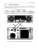
Before removal, disconnect power, RF, and any other interface connectors as well as the interconnecting
cables. On the rear of the units, remove any screws used to connect Transport brackets to the module. On the
front of the units, remove the four screws holding each front panel to the rack. Carefully slide each chassis out
of the front of the rack.
CAUTION:
Never rack-mount the TWTA using the front panel alone. The chassis is
likely to be damaged unless its weight is supported. Bottom support rails
must be provided in a rack mount configuration.
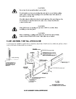
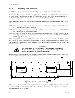
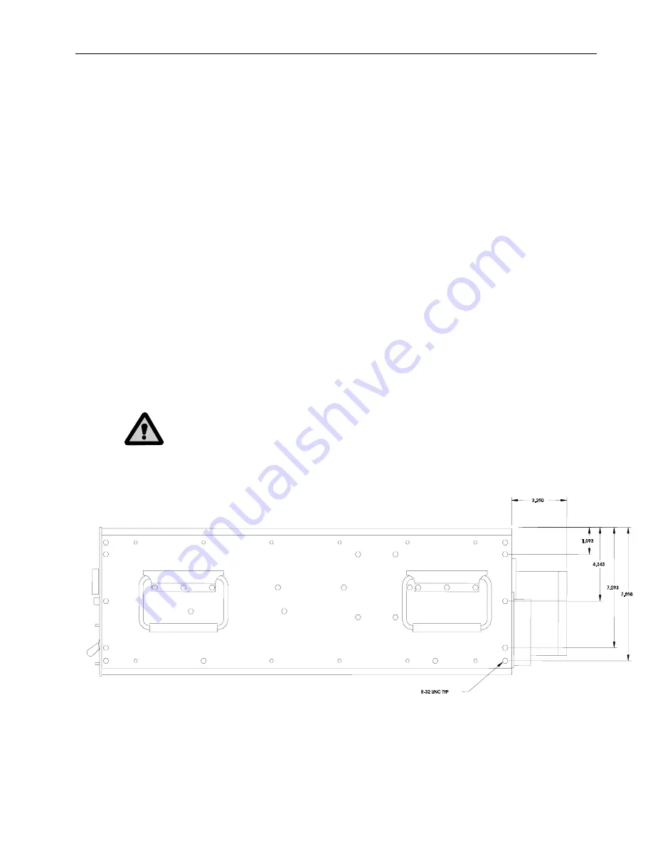
See Figure 3-1 (below) for the locations of threaded holes on the power supply/control module that may be
used for supplementary support of the rear of this unit.
Figure 3-1. Location of Threaded Support Holes
If bottom supports are used for rack mount installation of single or multiple units, the units should be
separated vertically by at least 1 3/4 inches. This will allow room for necessary support rails and facilitate
installation and removal of the units.
Summary of Contents for 10012342
Page 2: ......
Page 4: ......
Page 8: ......
Page 12: ......
Page 20: ......
Page 44: ...Model 500T8G18 30 Rev B ...
Page 48: ...Model 500T8G18 34 Rev B ...
Page 50: ...Model 500T8G18 36 Rev B ...
Page 56: ...Model 500T8G18 42 Rev B ...
Page 70: ...Model 500T8G18 56 Rev B ...
Page 72: ......

