


Model 500T8G18
Rev B
21
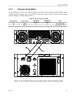
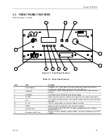
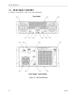
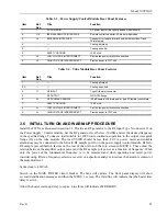
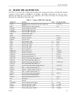
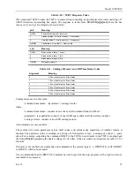
Table 3-3. Power Supply/Control Module Rear Panel Features
Item Ref.
Des.
Title Function
1.
1.
AC POWER IN
AC power input strain relief (3-phase model shown)
2.
J12
IEEE-488 REMOTE INTERFACE
Remote control connector: 24 pin hermaphrodite
3.
J2
EXTERNAL INTERLOCK
Connector for remote interlock and inhibit functions: D-sub
15-pin female
4.
-
—
Cooling air intake
5.
-
—
Cooling air outlet
6.
SAFETY GROUND
10-32 stud
7. J3
LOW
VOLTAGE
INTERCONNECT
Provide fan power, interlock connection
8.
J4
HIGH VOLTAGE INTERCONNECT
Provide power to TWT unit
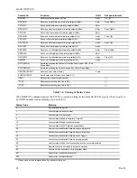
Table 3-4. Tube Module Rear Panel Features
Item Ref.
Des.
Title Function
1.
—
—
Cooling air intake.
2, 3.
—
—
Cooling air outlets.
4.
J1
RF INPUT
Type N (female) connector
5.
RF OUTPUT
WRD-750 flange
6.
J2
RF FORWARD SAMPLE
-50 dB sample of forward power, type N (female) connectors
7.
SAFETY GROUND
10-32 stud
8. J3
LOW
VOLTAGE
INTERCONNECT
Provide fan power, interlock connection
9.
J4
HIGH VOLTAGE INTERCONNECT
Provide power to TWT unit
3.6 INITIAL TURN ON AND WARM-UP PROCEDURE
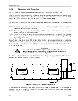
Install the TWTA as discussed in section 3.2 Provide an RF generator to the RF input Type N connector J1 on
the Power Supply / Control module. Set the RF generator level below -50 dBm and set the desired frequency
in the specified range. Connect a load suitable for 1000 watts continuous operation to the output waveguide
flange (J2) on the tube module. The load VSWR should be less than 2.0:1 A power meter and suitable
attenuators may be connected to the forward RF sample port J6 on the power supply/control module. Refer to
RF sample port calibration factors on the rear of the unit or on the
Info
screen in MENU 2. These show the
relation between the amplifier output power and the RF sample port power as a function of frequency. When
only the power of the fundamental frequency is to be measured and when operating near rated power,
consider using filters, a frequency selective receiver or a spectrum analyzer to reduce the harmonic content of
the measured level.
Set keylock to LOCAL.
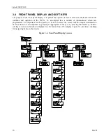
Switch on the MAIN POWER circuit breaker. The fans will operate. The front panel display will show
several identification messages and then the MENU 1 screen. The third line will indicate that the heater time
delay is active.
Allow the heater warm-up delay to expire. Line three will indicate OFF/READY.
Summary of Contents for 10012342
Page 2: ......
Page 4: ......
Page 8: ......
Page 12: ......
Page 20: ......
Page 44: ...Model 500T8G18 30 Rev B ...
Page 48: ...Model 500T8G18 34 Rev B ...
Page 50: ...Model 500T8G18 36 Rev B ...
Page 56: ...Model 500T8G18 42 Rev B ...
Page 70: ...Model 500T8G18 56 Rev B ...
Page 72: ......


