Model 350S1G6A
iii
2.6.6.13
Faults (350S1G6A) ........................................................................................ 24
2.6.6.14
Operating Hours (RF On) .............................................................................. 25
2.6.6.15
Operating Hours (Power On) ......................................................................... 25
2.6.6.16
AC Power-On Defaults .................................................................................. 26
3.
THEORY OF OPERATION ............................................................................. 27
3.1
Introduction .......................................................................................................... 27
3.2
RF Amplifier Operation ....................................................................................... 27
3.2.1
A1 Pre-Amp (Schematic 10035953) .................................................................... 27
3.2.2
A2, A8-A15 Driver Amps (Schematics 10035763, 10039088, 10035766) ......... 28
3.2.3
A2 through A55 Output Power Amplifiers (Schematics 10035763, 10039088,
10035766) ............................................................................................................ 28
3.2.4
A3 Two-Way Splitter ........................................................................................... 28
3.2.5
A6, A7, A16, A18, A19, A20, A21, A23 Four-Way Splitter ............................... 28
3.2.6
A56, A57 Twelve-Way Combiner ....................................................................... 28
3.2.7
A58 Two Way Combiner ..................................................................................... 28
3.2.8
A59 Dual Directional Coupler ............................................................................. 29
3.2.9
Detector Assembly ............................................................................................... 29
3.3
Power Supplies (PS1, PS2, PS3 and PS4) ............................................................ 29
3.3.1
A65 Regulator Board (Schematic 10047637) ...................................................... 29
3.4
Control System ..................................................................................................... 30
3.4.1
A60A1, A60A3 Display Assembly, 4.3” LCD (Schematics 10029679,
10030013) ............................................................................................................ 30
3.4.2
A61 Interface Board (Schematic 10020073) ........................................................ 30
3.4.3
A66 ALC Board (Schematic 10023927) .............................................................. 30
4.
MAINTENANCE ............................................................................................... 31
4.1
General Maintenance Information ........................................................................ 31
4.2
Disassembly Procedure ........................................................................................ 31
4.3
Troubleshooting ................................................................................................... 32
4.3.1
General - Reading Faults ...................................................................................... 33
4.3.2
The Unit Cannot Be Operated Remotely .............................................................. 33
4.3.3
Thermal Fault (Schematic 10047656) .................................................................. 33
4.3.4
Interlock Fault (Schematic 10047656) ................................................................. 34
4.3.4.1
INTERLOCK FAULT ................................................................................... 34
4.3.4.2
AC INTERLOCK FAULT ............................................................................ 34
4.3.5
Power Supply Faults (Schematic 10047656) ....................................................... 34
4.3.5.1
PS2, PS3 and PS4 Fault (DC OK) ................................................................. 34
4.3.6
Amplifier Faults (Schematics 10047656 and 10039045) ..................................... 35
4.3.7
ALC Fault ............................................................................................................. 35
4.3.8
Low or No Power Output (DC Tests) (Schematic 10047656) ............................. 35
4.3.9
Low or No Power Output (RF Test) (Schematic 10047656) ............................... 36
FIGURES
2-1
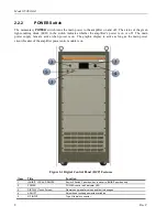
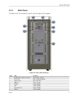
Digital Control Panel (DCP) Features .................................................................... 8
2-2
Rear Panel Features ................................................................................................ 9
2-3
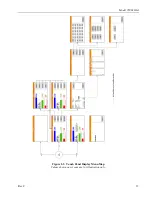
Touch Panel Display Menu Map .......................................................................... 11
4-1
Typical Response at 0 dBm Input and -20 dBm Input ......................................... 36
4-2
Typical Response: Input A3 to Quad Final Module RF Output ........................... 37
4-3
Typical Quad Amp Response ............................................................................... 37
4-4
Typical Four-Way Splitter Insertion Loss ............................................................ 38
4-5
Typical Twelve-Way Combiner Insertion Loss ................................................... 39
4-6
Typical Twelve-Way Combiner Return Loss: Combined Output Port ................ 39


