Model 350S1G6A
12
Rev C
2.3.1
RF GAIN Control
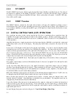
The RF GAIN control, which has a minimum of 10dB of range, is used to adjust the input attenuator of the
preamplifier-leveler module. This control simply adjusts the output power level for a fixed input power level.
To adjust the RF Gain, press the Select button from the main menu and then press the RF Gain button in the
subsequent menu. Adjust the value using the adjust knob. Please note that the display panel is limited in
resolution compared to the control signals, which are generated and sent to the leveler electronics module.
2.4 INPUTS AND OUTPUTS
The input and output connectors described in the following sections are located on the unit’s front or rear
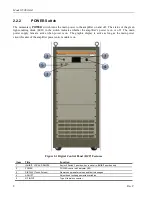
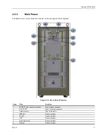
panels; refer to the Front and Rear Panel Features drawings (Figure 2-1, Figure 2-2).
2.4.1
RF Input
This Type N connector is the RF input to the amplifier. It should be connected to a RF signal generator or
sweep generator.
2.4.2
RF Output
This Type 7/16 connector is the RF output of the amplifier.
It should be connected to a suitable 50Ω load.
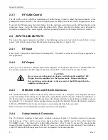
For proper connection to the RF output connector a torque of 221 in-lbs. (24.97 N-m) shall be used.
CAUTION:
Do not connect or disconnect any loads or cables from the amplifier’s RF
Output when the amplifier is in the Operate mode. Dangerous voltages
that could cause serious injury to the user exist at the RF Output when the
amplifier is under power.
2.4.3
IEEE-488, USB, and RS-232 Interfaces
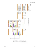
The Model 350S1G6A’s remote interfaces allow remote control, via a computer, of all amplifier functions
(except for the Keylock Switch position) that can be controlled from the front panel. When the amplifier is in
the Remote mode (as determined by the position of the Keylock Switch), a special Remote display is shown
(see Figure 2-3). Front panel controls are deactivated, except for the Keylock Switch, which can be rotated to
LOCAL or INHIBIT in order to prevent remote control commands from being executed.
Refer to Section 2.6 for information on remote operation of the amplifier.
2.4.4
Safety Interlock Connector
The 15-pin D-sub miniature female safety interlock connector (Figure 2-2, Item 4) provides two separate
interlock loops. Pins 1 and 8 are used for situations where the amplifier can be left on but forced into
STANDBY mode. This interlock is called Inhibit Interlock. Pins 10 and 14 are used for situations that
demand the safest possible condition, with the AC power to all main circuits disconnected. This interlock is
called AC Interlock. Both loops must be closed, or jumpered, for normal operation.


