Model 350S1G6A
Rev C
37
2.
Remove the coaxial cable from the output of the A2 connector to the input of the A3 Two-Way Splitter.
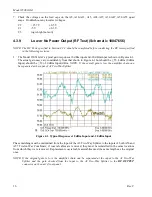
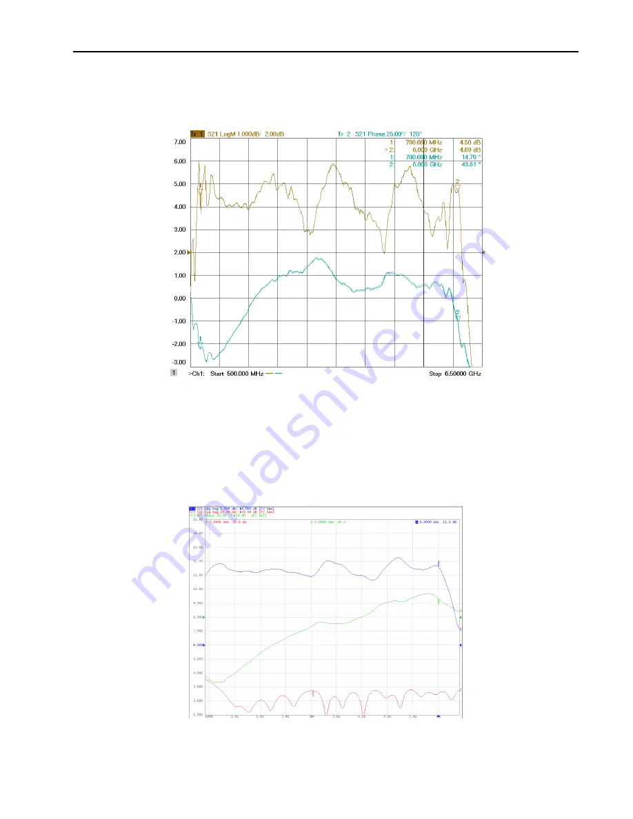
The typical Gain and Phase response from the input of the A3 Two-Way Splitter to the RF Output of a
Quad Power Module is shown in Figure 4-2.
Note: Make sure to terminate the combiner port that was
disconnected to measure the final module. This port should be terminated into a 50
Ω load.
Figure 4-2. Typical Response: Input A3 to Quad Final Module RF Output
If the response is normal, see Step 8. If the response is abnormal, perform the following tests.
3.
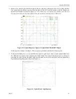
If the gain is slightly low (i.e., several dB below typical), repeat step 2 above in each module bank. Note
the difference in response when measuring the Quad Amps; if any Quad Amp causes less of a change in
gain than the others, check the Quad Amp, coaxial cable, and so forth associated with that Quad Amp.
Typical Quad Amp Response is shown in Figure 4-3
.
Figure 4-3. Typical Quad Amp Response

