Model 500A250D
Rev A
23
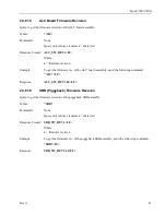
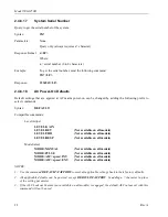
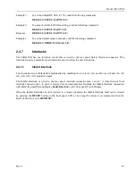
Example 1:
To set the default RF Gain to 75%, send the following command:
DEFAULT:LEVEL:GAIN75<LF>
Example 2:
To query the default RF Gain setting, send the following command:
DEFAULT:LEVEL:GAIN?<LF>
Response:
DEFAULT:LEVEL:GAIN75<LF>
Example 3:
To set the default mode to manual, send the following command:
DEFAULT:MODE:MANUAL<LF>
2.4.7
Interlocks
The 500A250D has one interlock circuit that is wired to the rear panel Safety Interlock connector. This
interlock requires a normally closed external circuit to allow the unit to function.
2.4.7.1
Inhibit Interlock
This interlock circuit inhibits RF amplification by disabling the low level (A1) and Power (A2 and A6, A8,
A9, A10, A12, A13) amplifier stages.
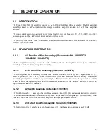
The Inhibit Interlock is wired to the rear panel interlock connector pins 1 and 8. A closed circuit from
interlock connector pin 1 to pin 8 is required for normal operation. Opening the Inhibit Interlock connection
will inhibit the amplifier and display
Fault:Interlock
on the front panel Touch Display.
When the Inhibit Interlock circuit is restored to a closed condition, the Inhibit Interlock fault can be cleared
by pressing the
RESET
button on the front panel LCD or by using the remote reset command (when the
Keylock Switch is set to
REMOTE
).
Summary of Contents for 500A250D
Page 2: ......
Page 4: ......
Page 6: ......
Page 18: ......
Page 22: ...Model 500A250D 4 Rev A ...
Page 25: ...Page 3 500A250D 500 watts CW 10kHz 250MHz Graphs ...
Page 26: ...Page 4 500A250D 500 watts CW 10kHz 250MHz Graphs ...
Page 28: ......
Page 46: ...Model 500A250D 24 Rev A ...
Page 58: ......


