Model 500A250D
Rev A
27
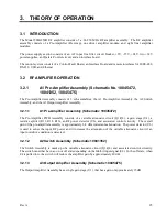
U5 is a comparator that monitors the output of U1 and generates a fault signal if the drain current varies
outside normal operating conditions. It also monitors the module temperature via a thermistor (R31) and
generates a fault signal if the module heatsink exceeds approximately 80
o
C
3.2.6
A24, A25, A26 Two-Way Combiners
A24, A25, and A26 are Two-Way combiners with impedance matching. The combiners operate in a zero-
degree configuration. The combiners are designed to tolerate loss of input signals at full output power.
3.2.7
A14 Three-Way Combiner
The Three-Way Combiner operates in zero-degree configuration with a broadband range of .01-250 MHz.
The combiner is designed to tolerate loss of input signals at full power.
3.2.8
A15 Bi-Directional Coupler
The A15 Bi-Directional Coupler takes a sampling of the forward and reverse RF output signal for use in the
automatic level control and display circuitry. The RF coupling of the forward and reverse coupled ports is
approximately 60 dB.
3.2.9
A16 Detector (Schematic 10045651)
The A16 Detector converts the RF signals from the bi-directional coupler to a DC voltage for use in the
automatic leveling, sample ports, and display circuitry.
3.3 POWER SUPPLIES (PS1, PS2, PS3)
Power supply PS1 supplies a +5VDC housekeeping supply for the control system assemblies A18
Control/Fault Board and A20 Interface Board.
PS1 also supplies -15 VDC at 2.5 amps. PS1 is a switching supply that automatically sets the AC input
circuits to the correct connections for the line voltage 200-240 VAC input ranges 50/60 Hz.
The -15 VDC at 2.5 amp power supply is fed to the A1 Pre-Amp, and A2 driver and A6, A8, A9, A10, A12,
A13 power modules.
The +24 VDC at 7.5 amps power supply is fed to all fan assemblies.
Power Supply PS2 is a single output supply which pr34VDC to the A2 driver and A10, A12, and
A13 power modules. Primary AC circuit protection is provided by the circuit breaker in the Power Entry
Module.
Power Supply PS3 is a single output supply which pr34VDC to the A6, A8 and A9 power modules,
and the A28 regulator assembly. Primary AC circuit protection is provided by the circuit breaker in the
Power Entry Module.
Summary of Contents for 500A250D
Page 2: ......
Page 4: ......
Page 6: ......
Page 18: ......
Page 22: ...Model 500A250D 4 Rev A ...
Page 25: ...Page 3 500A250D 500 watts CW 10kHz 250MHz Graphs ...
Page 26: ...Page 4 500A250D 500 watts CW 10kHz 250MHz Graphs ...
Page 28: ......
Page 46: ...Model 500A250D 24 Rev A ...
Page 58: ......


