Technical data
VECTOPOWER® VP600....
Modified: 2016.10.12 by Andreas Mangold
Printed: 2016.10.12
VECTOPOWER_VP0x00_xxxA1_Wx_xxx_Installationsanleitung_v1_20_en.doc
66
ARADEX
ARADEX
AG
ARADEX-AG
Ziegelwaldstr. 3
73547 Lorch Germany
Tel.: + 49/ (0)7172/ 9181-0
Hotline:
Fax: + 49/ (0)7172/ 9181-91
E-Mail: info@aradex.com
http:/ / www.aradex.com
+ 49/ (0)700-
A maximum output current of 0.2
A is permitted per output.
Each output has a short-circuit-proof design and is equipped with overtemperature pro-
tection to protect against overloading. In the case of overheating, the corresponding
output is switched to inactive.
The internal resistance of the driver stage is max. 4
Ω.
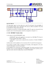
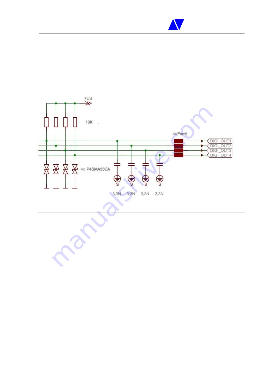
Figure 59: Protective circuit of the digital outputs
Sufficient pins must be available on the connectors ST2, ST3, and ST4 to use digital out-
puts.
The availability of this function and the pin assignment can be found in the data sheet
of your VECTOPOWER
®
.
3.7.5.14
DC link voltage measurement function block
Each device of the VECTOPOWER
®
series internally measures the applied DC link volt-
age. This causes the power stage to switch off in the case of overvoltage. The operator
must make sure that no excessive DC link voltage occurs as a result of the motor, the
operating mode, or the supply. The DC link voltage measurement is only able to stop
the feedback when an excessive voltage is detected in the case of a DC link failure when
feedback is used. If the DC link voltage increases due to external influences, the VEC-
TOPOWER
®
device will still be damaged.

