Installation
VECTOPOWER® VP600....
Modified: 2016.10.12 by Andreas Mangold
Printed: 2016.10.12
VECTOPOWER_VP0x00_xxxA1_Wx_xxx_Installationsanleitung_v1_20_en.doc
84
ARADEX
ARADEX
AG
ARADEX-AG
Ziegelwaldstr. 3
73547 Lorch Germany
Tel.: + 49/ (0)7172/ 9181-0
Hotline:
Fax: + 49/ (0)7172/ 9181-91
E-Mail: info@aradex.com
http:/ / www.aradex.com
+ 49/ (0)700-
DANGER!
Fuses
Make sure that semiconductor fuses are integrated in the DC link line, in
order to ensure isolation in the case of a fault.
CAUTION!
Make sure that no conductive objects or dirt enters the VECTOPOWER
®
device when you open the cover.
Motor phases
When the motor phases are connected, the correct assignment of the
phases must be ensured.
In order to establish the line connection, proceed as follows:
1. Make sure that there is no DC link voltage any more at the feed line from the bat-
tery or the supply for the DC link. Secure the DC link against being switched on
again.
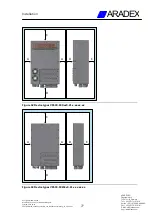
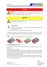
2. Next, only open the red-marked screws of the device cover.
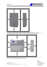
Figure 67: Opening the access cover
Never loosen the screws of the cover itself. Make sure that the seal has not been
destroyed.
Next, remove the cover plate.
3. Remove the screw fittings for the DC link connections. Push the feed line through
the screw fitting. Here you have to observe the permissible cross-sections or external
diameters of the screw fittings. Squeeze the wire terminal onto your line. Make sure
that the shielding is applied correctly.
4. Push the wire terminal through the opening and place it at the appropriate posi-
tion in the device. Observe the polarity for the DC link connections or the correct
sequence for the motor phases.


