background image

4.3

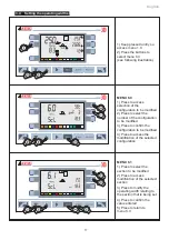
Selection of the flow rate of the sprayer booms

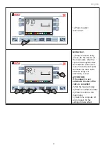
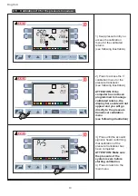
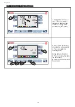
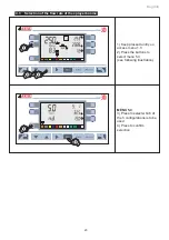
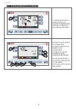
1) Keep pressed until you

access menu 1.0
2) Press the buttons to

select menu 5.0

(see following illustration)

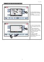
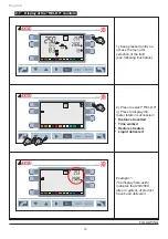
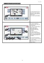
MENU 5.0

3) Press to select which of

the 5 configurations is to be

used
4) Press to confirm

selection

English

23

Summary of Contents for Bravo 3 Series

Page 1: ...BRAVO 3XX SOFTWARE 60 VERSION ADDITION TO INSTRUCTION BOOKLET CODE D20033 GB...

Page 2: ...e to which it refers and must always accompany it even in case of sale or transfer Keep it for future reference ARAG reserves the right to modify the spe cifications and instructions regarding the pro...

Page 3: ...ences compared to the version for the spraying machine 14 3 2 Programming of the flow rate for the sectors 15 3 3 Selection of the flow rate of the sectors 16 3 4 Setting the operating widths 17 3 5 S...

Page 4: ...amount Setting the minimum speed for the automatic closure of the main valve Menu 191 0 192 1 section 2 4 it is possible to set a speed so that the main valve will be closed automatically below this o...

Page 5: ...pressed until you access menu 1 0 2 Press to select menu 4 0 see following illustration MENU 4 0 3 Press to select the nozzle whose pressure alarms require setting 4 Keep pressed until you access the...

Page 6: ...h an alarm will be triggered visual and acoustic 7 Press to return to menu 4 0 During data modification A Press to modify the data you are setting B Press to confirm the new data entered 2 2 Incorrect...

Page 7: ...2 Press to set code 76 3 Press to confirm the code MENU 191 0 1 Press to set the value for the minimum speed below which automatic adjustment will be blocked 2 Set the required value 3 Press to confi...

Page 8: ...ns pressed together in order to access advanced user programming 2 Press to set code 76 3 Press to confirm the code MENU 191 0 1 Press to set the value for the minimum speed km h or mph below which au...

Page 9: ...um value set in menu 191 0 the computer will close the main valve after the delay set previously is over ATTENTION If the value 0 is set automatic closure of the valve is cancelled 2 Set the required...

Page 10: ...NTION If the computer has not been programmed to manage calibrated returns the display here aside will not appear and you will go directly to the pressure transducer calibration menu see following ill...

Page 11: ...ng the tank see following illustration 2 Press to access setting for the liquid present in the tank 3 Press both buttons together in order to reset the value for the remaining liquid shown by the comp...

Page 12: ...ield see following illustration 2 Press to select FIELD 0 3 Press to display the meter totals in succession Distance travelled Time worked Hectares treated Liquid delivered Example 1 The display here...

Page 13: ...ay here aside indicates that a distance of 15 km or miles has been travelled 2 8 Pump failure signal Should pump failure be detected these symbols will be displayed and an acoustic alarm signal will b...

Page 14: ...w rate of the sectors section 3 3 Setting the operating widths Menu 6 0 6 1 section 3 4 this menu is used to store 5 operating widths Menu 6 0 Cnf X for each of these the operating width must be enter...

Page 15: ...ns requires modification 2 Press to select the sector whose flow rate requires setting 3 Press to set the flow rate value for the selected sector 4 Press to set the pressure value relating to the flow...

Page 16: ...f the sectors 1 Keep pressed until you access menu 1 0 2 Press the buttons to select menu 5 0 see following illustration MENU 5 0 3 Press to select which of the 5 configurations is to be used 4 Press...

Page 17: ...the number of the configuration to be modified 3 Press to confirm the configuration to be modified 4 Press to access the modification of the selected configuration MENU 6 1 1 Press to select the secti...

Page 18: ...selection of dosing l ha and the operating width see following illustration 2 Press to set the dosing amount l ha to be applied 3 Press to modify the operating width During data modification A Press...

Page 19: ...ect the operating programme for configuration 3 Press to set the dosing l ha that is to be associated with the operating programme selected 4 Press to access selection of the operating width to be ass...

Page 20: ...eep pressed until you access the menu for the selection of the operating programme see following illustration 2 Press to select one of the 12 operating programmes previously set 3 Press to confirm sel...

Page 21: ...is fitted with more than two sprayer booms the data must be set adjustment is carried out by means of the pressure transducer you require the correct pressure to be shown on the display without using...

Page 22: ...requires modification 2 Press to select the sprayer boom whose flow rate requires setting 3 Press to set the flow rate for the sprayer boom selected 4 Press to set the pressure relating to the flow ra...

Page 23: ...he sprayer booms 1 Keep pressed until you access menu 1 0 2 Press the buttons to select menu 5 0 see following illustration MENU 5 0 3 Press to select which of the 5 configurations is to be used 4 Pre...

Page 24: ...r configuration see following illustration 2 Press to set the amount for dosage l ha 3 Press to select the row distance to be used modified 4 Press to access the modification of the operating width se...

Page 25: ...tration 2 Press to select the operating programme for configuration 3 Press to set the amount for dosing l ha to be associated with the operating programme selected 4 Press to select one of the five r...

Page 26: ...select one of the 12 operating programmes set previously 3 Press to confirm selection of the operating programme 4 7 Signalling of ambiguous section opening Should the number of open sections on one s...

Page 27: ......

Page 28: ...tain safety conditions foreseen by the constructor Always refer to the ARAG spare parts catalogue D30008 GB m01 07 2005 Via Palladio 5 A 42048 RUBIERA Reggio Emilia ITALY Tel 0522 622011 Fax 0522 6289...

Reviews: