20
USE
15
USE
15.1
BLC - OPERATION
15.2
Fixed geometry
The BLC control considers the boom as a single body: it is then a
fixed geometry
control as the division at boom section is negligible.
The boom
must be COMPLETELY open.
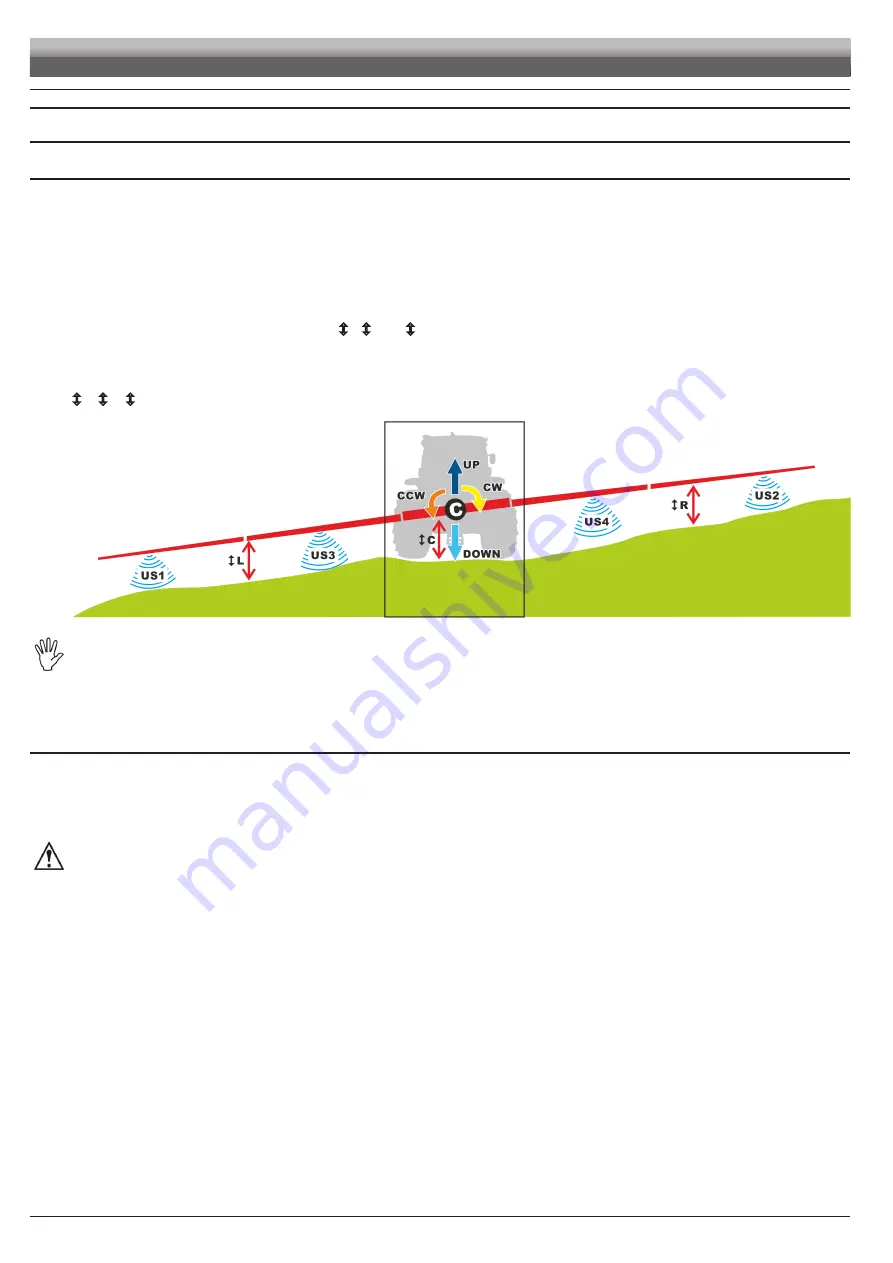
To the keep the boom in the desired position, the BLC control performs two types of independent corrections at the same time:
• Boom leveling
The boom rotates with respect to the center (
C
in
Fig. 34
) of the mechanical arm, leveling the inclination with respect to the crop.
1
Counter-clockwise rotation (orange -
CCW
),
2
Clockwise rotation (yellow -
CW
),
• Boom height control
The boom moves vertically controlling the height (
L
,
C
and
R
in
Fig. 34
) with respect to the crop.
3
Lifting (blue -
UP
)
4
Lowering (light blue -
DOWN
),
The ultrasonic sensors (
US1
÷
US4
in
Fig. 34
) installed on the boom provide the data required for the correction, determining the distances
L
/
C
/
R
from boom to crop.
Fig. 34
WARNING
• Ultrasonic sensors do not distinguish between crop and soil as they detect the first object encountered.
Boom height is the distance between the arm and the crop (when present).
• The boom, during leveling, rotates with respect to the boom instantaneous center of rotation (
C
POINT).
15.3
Hydraulic control
Thanks to the IBX100 hydraulic control unit the BLC control automatically activates:
• the leveling and boom height control hydraulic functions
• system hydraulic drain valve (pilot valve)
Check that the hydraulic system and the valves are connected to the IBX100 hydraulic control unit.
WARNING: DURING AUTOMATIC LEVELING, THE SYSTEM ACTIVATES THE PILOT VALVE, HENCE THE HYDRAULIC CIRCUIT IS
PRESSURIZED.
OTHER HYDRAULIC FUNCTIONS (MOVEMENTS, DRIVES, ETC...) CONNECTED TO THE SAME SYSTEM CAN BE ACTIVATED BY
SENDING THE CONTROL ONLY TO THE SUITABLE VALVE, SINCE THE PILOT VALVE IS ALREADY ACTIVATED BY THE BLC. MAKE
SURE THAT THIS DOES NOT JEOPARDIZE MACHINE SAFETY.


