background image

© 2016 Araknis Networks

®

68

Araknis Networks Wireless Access Point

Product Manual

Advanced Menu

-Return to Table of Contents-

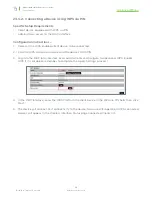
23.3.2 - Connecting a Device Using WPS via PIN

Specific Setup Requirements

•  Client device equipped with WPS via PIN
•  Administrator access to the WAP interface

Configuration Instructions – 

1.  Power on the WPS enabled client device to be connected.

2.  Find the WPS setup menu and record the device’s WPS PIN.

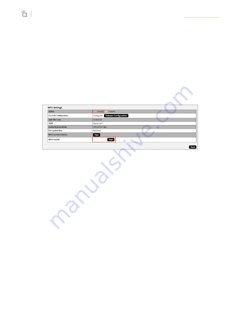
3.  Log into the WAP local interface as an administrator and navigate to Advanced, WPS. Enable 

WPS if it is disabled (remember to complete the Apply Settings process).

4.  In the WAP interface, enter the WPS PIN from the client device in the WPS via PIN field, then click 

Start.

5.  The device will connect. Test connectivity to the device to ensure WiFi operation. WPS-connected 

devices will appear in the Wireless Interface Status page Connected Clients list.

Summary of Contents for AN-100-AP-I-N

Page 1: ...WIRELESS ACCESS POINT PRODUCT MANUAL Models AN 100 AP I N AN 300 AP I N AN 500 AP I AC AN 700 AP I AC ...

Page 2: ... installation setup or use of the product that is not essential to follow for safety of the equipment or user Notes may be located before or in the midst of the section to which they apply depending on the type of information These items usually contain essential information like the size or dimension of a separate part required or a critical step in the process that if missed would cause the inst...

Page 3: ...p Shelf 11 6 2 Junction Box Mounting 11 Instructions 11 6 3 Wall or Ceiling Drywall Mounting Instructions 12 6 4 Ceiling Tile Mounting Instructions 12 7 Power On and Operation 13 7 1 Status LED Operation 13 8 Introduction to Network Setup 14 9 Accessing the Web Interface 14 9 1 EZ Access Method Default 15 9 2 Configured System Name Access 16 9 3 DHCP Static IP Address Method 17 Finding the IP Addr...

Page 4: ...ireless Networks 38 15 5 Wireless Security Setup SSID Encryption 39 WEP Mode 39 WPA PSK Mixed and WPA2 PSK Modes 40 WPA and WPA2 Modes 41 15 6 Guest Network 42 15 7 Configuring the WAP as a Repeater 44 Repeater Mode Setup Instructions 45 16 Security Settings 46 16 1 User Accounts 46 16 2 Access Control 47 16 3 Email Alert 48 16 4 Device Discovery 50 17 Schedule 51 17 1 Auto Reboot Settings 51 17 2...

Page 5: ...IN 68 23 4 Site Survey 69 23 5 Spectrum Analyzer 70 Configuring Scan Settings 70 Running a Scan 70 Understanding Spectrum Analyzer Results 71 23 6 Wireless Traffic Shaping Settings 73 23 7 SNMP Settings 74 SNMPv2 Settings 75 SNMPv3 Settings 76 23 8 Spanning Tree Settings 77 23 9 VLAN Settings 78 24 Appendix 79 24 1 Configuring Guest Networks with Fast Roaming 79 25 Troubleshooting 82 25 1 Hardware...

Page 6: ...atures Feature AN 100 AP I N AN 300 AP I N AN 500 AP I N AN 700 AP I N 2 4GHz Radio Yes Yes Yes Yes 5GHz Radio No Yes Yes Yes Concurrent Dual band No Yes Yes Yes Gigabit Ethernet No Yes Yes Yes PoE Standard 802 3af 802 3af at 802 3af at 802 3af at WiFi Standard 802 11 b g n 802 11 a b g n 802 11 a b g n ac 802 11 a b g n ac OvrC Enabled Yes Yes Yes Yes Antennas 2x2 2 2x2 2 2x2 2 3x3 3 2 2 Package ...

Page 7: ... 3 Hardware Overview Use these images to familiarize yourself with the physical layout of your access point 3 1 Top Status LED Reset Button 300 500 700 Series Status LED Reset Button 100 Series 3 2 Bottom Rubber Feet 4 Power Ethernet Connections 300 500 700 Series 100 Series Ethernet Cable Knockout 3 3 Side Ventilation Holes ...

Page 8: ... 300 ft 100m radius actual performance varies based on multiple variables Plan multiple access points at least 200 ft apart Signal should overlap but only slightly Use network site survey tools not included to determine mounting locations if possible This will ensure you get the best coverage and performance from your installation Pro Tip Professional site survey tools are available from vendors i...

Page 9: ...e is required for longer runs 5 2 PoE Requirements Caution Use an 802 3af at compliant PoE injector switch or router to power the access point Non compliant devices can harm the access point and lead to unpredictable results 5 3 Power Requirements for Non PoE Application If PoE is not being used connect a suitable power supply not included from a nearby outlet to the DC input of the access point A...

Page 10: ...knis Networks 10 Araknis Networks Wireless Access Point Product Manual Wiring Requirements Return to Table of Contents 5 4 1 Wiring Diagram Figure 5 Network Wiring Diagram Mobile Apps ENABLED Web Browser Access ...

Page 11: ...Single Double Gang 4 Square Box 3 Octagonal Box 4 Octagonal Box 6 2 1 Instructions 1 Place the mounting bracket over the junction box and attach it loosely with 2 screws two 6 32 x 1 screws are included Use the hole pattern on the bracket that best matches the box pattern See Figure 6A below 2 Level or align the bracket with nearby objects for uniformity and tighten the screws enough to secure it ...

Page 12: ...ening and warping the bracket 4 Connect the wiring to the access point and push any extra wiring back into the opening See Figure 7B below 5 Snap the access point onto the bracket See Figure 7C below Figure 7 Drywall Mounting Figure 7A Figure 7B Figure 7C 6 4 Ceiling Tile Mounting Instructions 1 Place the bracket over the desired mounting location and align it with nearby objects for uniformity 2 ...

Page 13: ...l is being broadcast If so you may continue to the next section to begin configuring device access and software setup 7 1 Status LED Operation After installing the access point connect the network and power cables and check the status LED Once the LED remains illuminated no more flashes then the device is ready to be accessed for setup Figure 9 Status LED Location Status LED 300 500 700 Series Sta...

Page 14: ...ccess the web interface of the access point EZ Access Method Default method used for initial setup Connect your computer to the access point using Wi Fi Configured System Name Access Enter the device name instead of the IP address to access the web interface DHCP Static IP Address Method Can be used any time Connect your computer to the network wired or wirelessly and enter the IP address issued t...

Page 15: ...urn solid before beginning setup Figure 10 Default SSID WAP set to DHCP by default Network PC set to DHCP araknis_initial On your wireless network enabled computer 1 Disconnect any network cables from your computer 2 Make sure the wireless network card is set to obtain an IP address automatically DHCP mode 3 Connect your computer to the wireless network named araknis_initial 4 Open a web browser a...

Page 16: ...rk The setting is enabled by default 1 See section 13 System Settings on page 29 to set the system name 2 Apply the settings After configuration the WAP web interface may be accessed using the system name 3 Open a web browser and enter the configuration address for your WAP in this format Example System Name smith100 Enter into address bar http config smith100 wap 4 Enter the login credentials Def...

Page 17: ... the Access Point The WAP is configured to DHCP by default so that the DHCP server can assign an IP address when the WAP is connected to the network the DHCP server is usually the router This address can be used for accessing the web interface 1 Use one of these methods to find the IP address of the WAP Check the client table on your router Use a network scanner e g Fing to sniff the network The A...

Page 18: ...fault IP address 192 168 20 253 Use this method if the access point is not issued an IP address on the network or if access is required while not connected to a network 1 Connect your PC to the WAP using a network patch cable Computer WAP 2 On your PC open the Control Panel and left click Network and Internet 3 Left click Network and Sharing Center 4 In the left bar left click Change adapter setti...

Page 19: ...ntents 5 Right click the icon for the wired network connection and left click Properties 6 Left click to highlight Internet Protocol Version 4 TCP IPv4 then left click Properties 7 In the General tab left click Use the following IP address and enter the IP address and subnet mask IP Address 192 168 20 2 Subnet Mask 255 255 255 0 ...

Page 20: ...erface Return to Table of Contents 8 Left click OK to close Internet Protocol Version 4 TCP IPv4 Properties then left click OK to close Wireless Network Connection Properties 9 Open a web browser and navigate to http 192 168 20 253 Log in using the default credentials Username araknis Password araknis ...

Page 21: ...e the submenus under the Status Settings Maintenance and Advanced headings to configure and maintain the access point Click Apply Changes to review and apply changes made in menus B Main Window The main window displays the currently selected submenu C Top Bar The top bar displays the current connection status to the OvrC server the current internally set system time and the current system uptime i...

Page 22: ...in the Web Interface 1 After making changes to settings on a menu page left click the Save button on the menu to hold the new settings in the Apply Changes field 2 After all desired changes have been made left click Apply Changes to review the new settings 3 Left click Apply to make the changes or Revert to cancel the changes Figure 15 Applying Changes ...

Page 23: ...ttings and information for the 2 4GHz channel The 300 500 700 Series will indicate settings and information for the 2 4GHz and 5GHz channels 11 1 System Information Displays current information about the WAP s system settings Figure 16 System Information Table Path Status System System Information Parameters System Name Name assigned to the system Used for configured name access Service Tag Intern...

Page 24: ...the 2 4GHz and 5GHz channels MAC Address Media Access Control MAC address The 2 4GHz and 5GHz channels each have individual MAC addresses Number of Networks Number of active wireless networks i e SSID s configured on the radio interface Number of Connected Clients Number of currently connected wireless clients on all configured networks using the radio interface Operation Mode Indicates whether th...

Page 25: ...Amount of data in bytes transmitted over the wired network connection RX Amount of data in bytes received from the wired network connection IP Address Access point IP address issued by the network router Subnet Mask Access point subnet mask Default Gateway Network router IP address Primary DNS Indicates the primary DNS for the device Secondary DNS Indicates the secondary DNS for the device 11 4 Sy...

Page 26: ...4GHz channel The 300 500 700 Series will indicate settings and information for the 2 4GHz and 5GHz channels Interface Status Indicates whether the wireless antenna is enabled or disabled Operation Mode Indicates whether the antenna is operating in Access Point or Repeater mode Wireless Mode Indicates whether the antenna is operating in 802 11b g n 802 11a n or 802 11ac n mode Channel Bandwidth Ind...

Page 27: ...less network settings Figure 21 Wireless Network Status Path Status Wireless interface Wireless Network Parameters Note The 100 Series will indicate settings and information for the 2 4GHz channel The 300 500 700 Series will indicate settings and information for the 2 4GHz and 5GHz channels Wireless Network SSID Network names SSID s being transmitted by the access point Enabled Indicates whether t...

Page 28: ...etwork SSID Indicates the SSID being used by a connected wireless client Interface Indicates the channel frequency of a connected wireless client MAC address Indicates the MAC address of a connected wireless client TX KBytes Amount of data in kilobytes transmitted to a connected wireless client RX KBytes Amount of data in kilobytes received from a connected wireless client RSSI dBm Indicates the w...

Page 29: ...ng the password Default araknis Admin New Password Enter a new login password Use letters numbers or punctuation Limited to 32 characters including spaces Confirm Admin New Password Confirm a new login password enter same password as above System LED Turn the Status LED ON or OFF Default ON Management VLAN The VLAN ID from where the WAP web interface must be accessed Default Untagged Caution Chang...

Page 30: ...and date four digits for year two digits for month two digits for date Time Enter the hour and minutes for the correct current time Use a mobile device or satellite clock for accuracy Synchronize with PC Click this button to automatically sync the access point to a connected computer Automatically Get Date and Time Select to automatically get date and time from various web resources NTP Server Sel...

Page 31: ...ate time zone from the drop down Enable Daylight Saving Select to enable DST start end can change from year to year Be sure to update this information Start Select the month date day and time Daylight Saving Time starts from the drop downs End Select the month date day and time Daylight Saving Time ends from the drop downs Configuration Instructions 1 Click Settings System 2 Specify the time zone ...

Page 32: ...nformation IP address IP Address Uncheck DHCP Enable to enter a static IP address for the device A static IP address is recommended Warning Use an IP address that is outside the DHCP server range to avoid duplicate addresses in the network Subnet Mask Enter the subnet mask for the device Default 255 255 255 0 Default Gateway With DHCP disabled enter the default gateway for the access point network...

Page 33: ...to configure LAN speed and duplex settings Figure 27 Interface Settings Path Settings LAN Interface Settings Parameters Speed Select LAN speed from Auto 1Gbps 300 500 700 Series only 100Mbps 10Mbps Disable turns the LAN Port OFF Default Auto Duplex 10 100Mbps modes only Select the duplex setting between the access point and the network router from Half or Full Default Full Configuration Instructio...

Page 34: ...ireless Mode Select the wireless mode for the radio Default 2 4GHz 802 11b g n 5GHz 802 11a n 300 802 11ac n 500 700 Operating Channel Select the desired Wi Fi channel Use a different channel than other WAPs on the network On the 2 4GHz radio there are only three non overlapping channels 1 6 and 11 Select a channel as far away from close numbered channels as possible Default Auto Pro Tip In a mult...

Page 35: ...es connected to the access point SSID s Available Total number of SSID s available 15 3 Global Wireless Settings Configure Band Steering and Fast Roaming Figure 30 Global Wireless Settings Path Settings Wireless Global Wireless Settings Parameters Band Steering 300 500 700 Series only This feature pushes clients to the 5 GHz radio if a client is compatible We recommend enabling this feature for th...

Page 36: ...interference Advanced Wireless Settings Does it matter what operating channel is used If you aren t using Auto Operating Channel selection use a different wireless radio channel in each WAP to lower the amount of interference each device encounters Do fast roaming and band steering work together Yes configure each one based on individual needs Remember some devices may not be compatible with these...

Page 37: ...Fast Roaming ON 3 Click Save and then Apply Changes to enable the new settings 4 Repeat steps 1 3 in the remaining WAPs 5 After setup test the new settings using several client devices You should see the client device listed in each WAP s Connected Clients table Path Status Wireless Interface 15 3 1 2 Fast Roaming Troubleshooting If certain devices don t work once Fast Roaming is enabled try turni...

Page 38: ... ON Default Yes Checked Name SSID Enter the network name for the network being configured Default araknis_initial Blank when adding a new network Note Be sure to change the SSID The default settings are not secure Interface Select 2 4GHz 5GHz or Both Channel Frequency Default Both 2 4GHz when adding a network Security Mode Configure the security mode for each wireless network Select a security mod...

Page 39: ...re 32 Wireless Security WEP Mode Path Settings Wireless Wireless Networks Security Mode Parameters Name SSID The name of the network being configured Security Mode Select a different encryption mode from the drop down Auth Type Select Open System or Shared Key mode from the drop down Input Type Select Hex or ASCII from the drop down Key Length Select 64 or 128 bit encryption from the drop down Def...

Page 40: ...PA2 PSK AES WPA2 PSK Mixed Both TKIP AES Passphrase Enter the appropriate passphrase for the wireless network being configured If using the ASCII format the password must be 8 63 characters in length If using HEX the password must be 64 HEX characters in length Default Blank Group Key Update Interval Enter a value to specify how often in seconds the Group key changes RANGE 30 3600 seconds Default ...

Page 41: ...t number Default 1812 This is a dedicated TCP UDP port and typically should not be changed Radius Secret Enter the Radius Server connection secret Default Blank Radius Accounting Enable or disable Radius Accounting Default Disable Radius Accounting Server Enter the Radius Accounting Server IP address Default Blank Radius Accounting Port Enter the Radius Accounting Server connection port number Def...

Page 42: ... SSIDs created using the Guest Network feature To create guest SSIDs with Fast Roaming see section 24 1 Configuring Guest Networks with Fast Roaming on page 79 Figure 35 Guest Network Path Settings Wireless Guest Network Parameters Enable Check the box to enable a guest network Default Disabled Name SSID Enter an SSID for the guest network Default Araknis 2 4_GuestNetwork Araknis 5 0_GuestNetwork ...

Page 43: ...lt Selected Manual IP Settings Settings for the guest network DHCP server All guest clients are placed on a different subnet as configured in this area Gateway IP Address Enter the Guest Network Gateway IP address Default 192 168 200 1 Subnet Mask Enter the subnet mask for the Guest Network Gateway Default 255 255 255 0 Automatic DHCP Server Settings Configure the IP addresses issued to guest clie...

Page 44: ...always better to get a wire to a WAP location than to use repeater mode Special Setup Requirements At least one WAP with a wired LAN connection Additional WAP s with local power but no LAN connection must be in range of the wired WAP SSID configuration on each WAP Installation Notes Do Fast Roaming and Repeater mode work together Not for the radio being used as a repeater Fast Roaming is not requi...

Page 45: ...3 Scroll down to the Repeater table on the same page and enter the SSID from the wired WAP in step 1 Repeater SSID Enter an SSID name for the repeater WAP connection Interface Displays the interface frequency set for repeater mode Security Enter the security credentials for the SSID from the wired WAP in step 1 Target SSID Enter the SSID from the wired WAP configured in step 1 Preferred BSSID Opti...

Page 46: ...w username for logging into the access point Use letters numbers or punctuation Limited to 32 characters including spaces Default araknis Blank when adding a new account Privilege Level Indicates the level of device management for the logged in user OPTIONS admin Status Status Settings Default admin Status Settings when adding a new account Password Enter a new login password Use letters numbers o...

Page 47: ...ble or Disable to enable or disable the ability to modify the device via Web Browser Default Enable Caution Disabling web access will cause a loss of connection to the web interface If this occurs regain connectivity by restoring the hardware to factory default settings Press Reset button for 10 seconds Telnet Enable or Disable the ability to modify the device via a command line interface CLI thro...

Page 48: ...nter the email address of the recipient Default Blank Subject Information regarding the nature of the system condition Default Email Alert araknis 88 DC 96 1D 33 6B Configuration Changed Email Account Username Enter the username for the email account Outlook Gmail etc sending the alert Default Blank Password Enter the password for the email account Outlook Gmail etc sending the alert Default Blank...

Page 49: ...le of Contents Figure 39 Common Email Client Ports Email Client Ports TLS Ports SSL Gmail 587 465 Outlook 25 or 587 Microsoft Exchange 25 465 Yahoo 465 Office 365 587 Configuration Instructions 1 Click Settings Security 2 Specify the email alert settings 3 Click Save then Apply Changes to enable the new settings ...

Page 50: ...un on devices running a Microsoft OS Default Disable UPnP Enable to allow the access point to search for and connect to network devices via UPnP Protocol Universal Plug and Play Default Disable Araknis EZ Access Use a URL to access the web interface see section 9 2 Configured System Name Access on page 16 Default Enable Caution If VLANs are enabled this setting will automatically become disabled I...

Page 51: ... network performance by keeping the system memory clear and ending unnecessary connections Figure 41 Auto Reboot Settings Path Settings Schedule Auto Reboot Settings Parameters Status Enable or Disable Auto Reboot Default Disable Date Check the boxes for the WAP should reboot on Time Enter the time for the reboot to take place in 24 hour format 00 00 midnight subtract 12 hours from 24 hour time fo...

Page 52: ...Displays the gateway IP address to be pinged usually the router Get Current Gateway IP Click to pull the current IP address of the gateway Delay Between Timeouts How many seconds the WAP waits to try a new ping after a timeout Default 30 seconds Timeout Attempts Before Reboot Number of timeouts that must occur before a reboot occurs Default 10 Ping Delay After Auto Reboot How many minutes before t...

Page 53: ...te different Wi Fi schedules using templates as detailed below Choose a Template Select the template that matches the schedule requirements Always Available 00 00 24 00 The wireless network is always ON Available 8 17 Daily 08 00 17 00 The wireless network is ON at 8 00AM and OFF at 5 00PM Available 8 17 Daily Except Weekends 08 00 17 00 The wireless network is ON at 8 00AM and OFF at 5 00PM Monda...

Page 54: ... SSID Market 2 3 Select an option from the Schedule Templates drop down to use In our example we will select Available 8 17 Daily since this template is closest to the schedule needed 4 Change the Schedule Table to work on the desired schedule In our example we will make the following changes Sunday Set to Unavailable so that no access is available the entire day Monday Friday Set to Available and...

Page 55: ...main Name Enter the IP address of a device or web page to determine if it can be reached Ping Packet Size Enter the packet size of each ping Maximum size 65535 Default 64 Bytes Number of Pings Enter the number of ping attempts Default 4 Start Click the Start button to send the Ping Ping Test results will be displayed in the text frame Ideal results Same number of packets transmitted received 0 pac...

Page 56: ...47 Traceroute Test Path Maintenance Traceroute Parameters Target IP Domain Name Enter the IP address of a device or web page to show the path of communication to that device or website Start Click the Start button to start Traceroute Traceroute Test results will be displayed in the text frame Stop Click the Stop button to stop Traceroute Configuration Instructions 1 Click Maintenance Traceroute 2 ...

Page 57: ...1 Click the To PC button and select a location to save the file 2 Name the file and save it to your computer 20 1 2 Upload New Configuration File Restore previously saved configuration settings to the access point to restore settings 1 Click the Choose File button and select a configuration file tar file type from the Open window 2 The file name will appear to the right of the Choose File button a...

Page 58: ...aults Configuration Instructions 1 Click the Yes button to restore the access point to factory default settings The red ALERT message will appear 2 Click Confirm to restore factory defaults Wait while the rebooting screen is open and loading the selected configuration When the configuration upload is finished the login window will appear 3 Enter the username and password araknis araknis 4 Confirm ...

Page 59: ...irmware was uploaded and activated Configuration Instructions 1 Click the Browse button to navigate to where the firmware file is saved 2 Select the file and then press Enter Return on the computer keyboard or click Open on the Upload menu The firmware file name should appear next to the Upload New Firmware File Browse button 3 Click Upload The Upload Firmware Information screen will open 4 Click ...

Page 60: ...e Restart Configuration Instructions 1 Click the Reboot the Device button The message This will reboot the device and may take a few seconds will appear 2 Click OK to reboot or Cancel to return to the Restart Screen 3 Wait while the access point reboots When the device has rebooted the login screen will appear 4 Enter the username and password 5 Confirm the firmware and configuration ...

Page 61: ...y close the browser tab or click Logout Closing the browser tab will close the setup screen completely Logout will end the session for the logged in user and open the Authentication Required Log In window Figure 53 Logout Alert Path Maintenance Logout Configuration Instructions 1 From any screen click Logout in the system menu The Logout ALERT will appear on screen 2 Click Cancel to return to the ...

Page 62: ...rate reduces throughput but increases the transmission range OPTIONS See drop down list Default Auto Transmit Power Select a setting from the drop down to set the radio power Higher power will improve performance but can cause interference with other access points in close range on the same channel Also a higher coverage range corresponds with lower throughput i e to achieve the highest transmit p...

Page 63: ... will indicate settings and information for the 2 4GHz and 5GHz channels Enable Select to enable Client Limit by channel Default Not Selected Max Client No Set the maximum number of clients that can be connected to a channel at a given time For 300 500 700 the maximum number of clients is set separately for each radio interface RANGE 1 127 Default 127 Pro Tip It is recommended to design the wirele...

Page 64: ...n enables disables Wireless MAC Filtering Figure 56 MAC Filter Settings Path Advanced MAC Filter MAC Filter Settings Parameters Enable MAC Filter Select Yes to enable MAC Filtering Default Not Selected Filter Mode Select Allow to permit wireless clients access to the wireless network as defined by wireless client MAC address Select Deny to prevent wireless clients from accessing the wireless netwo...

Page 65: ...he client number for a device being filtered by MAC address Default Not available if MAC Filtering is disabled client number is in the list if MAC Filtering is enabled MAC address The MAC address of a client being filtered by MAC address if MAC address filtering is enabled Default Blank Add Click to add a new client to be filtered by MAC address Delete Click to delete an existing client Configurat...

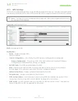
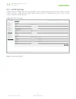
Page 66: ...PS feature is configured or unconfigured Release Configuration The primary SSID in the WAP will be reset to default if Release Configuration is clicked and then settings are applied Self PIN Code The WPS pin generated by the WAP SSID Displays SSID used for WPS Will always be the first SSID in the list on the Wireless Settings page WPS cannot be used unless this SSID is enabled checked Authenticati...

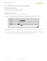
Page 67: ...ions 1 Power on the WPS enabled client device to be connected 2 Log into the WAP local interface as an administrator and navigate to Advanced WPS Enable WPS if it is disabled remember to complete the Apply Settings process 3 Press the WPS button on the client device then click the WPS via Push Button Start button in the WAP interface 4 The device will connect Test connectivity to the device to ens...

Page 68: ...client device to be connected 2 Find the WPS setup menu and record the device s WPS PIN 3 Log into the WAP local interface as an administrator and navigate to Advanced WPS Enable WPS if it is disabled remember to complete the Apply Settings process 4 In the WAP interface enter the WPS PIN from the client device in the WPS via PIN field then click Start 5 The device will connect Test connectivity t...

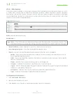
Page 69: ...annels Select Interface Select whether to scan for 2 4GHz or 5GHz networks Scan Nearby Networks Click the Scan button to begin a scan Result Displays information about found networks after the scan is complete BSSID Basic Service Set Identification Indicates the MAC address of a detected 2 4GHz or 5GHz neighboring access point SSID Service Set Identifier Indicates the network name of a wireless ne...

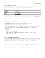
Page 70: ...ts Default 75 Scan Action Start Click to begin a scan Play Pause Click to pause an in progress scan Click again to resume the scan Stop Click to stop a scan Elapsed Time Amount of time since the Start button was pressed 23 5 1 Configuring Scan Settings The Spectrum Analyzer uses scan settings based on the configuration of the 2 4 or 5 Ghz radio interface To change the Scan Bandwidth and Channel se...

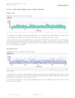
Page 71: ...ser to zero to see if spikes of activity become more obvious at certain frequencies As long as client devices connect at stronger RSSI values than the selected scan setting wireless traffic should not be adversely affected by the activity indicated on the graph Waveform View Figure 62 Spectrum Analyzer Waveform View The Waveform view shows the aggregate energy recorded at each scanned frequency Ma...

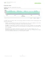
Page 72: ...ew If the current reading is closer to the maximum than the average the frequency should typically be avoided Average Average power of Waveform view data since since the scan began This view averages across time as well as data points for any one frequency Avoid frequencies with spikes above the rest of the graph Maximum Maximum power of Waveform view data since since the scan began This is the ma...

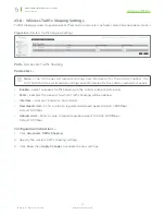
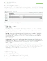
Page 73: ...GHz channel The 300 500 700 Series will indicate settings and information for the 2 4GHz and 5GHz channels Enable Select to enable Traffic Shaping on the 2 4GHz and or 5GHz band SSID Indicates the network to which Traffic Shaping will be applied Interface Indicates 2 4GHz or 5GHz band Download Limit Enter a value to regulate download speed RANGE 1 999Mbps Default 100Mbps Upload Limit Enter a value...

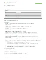
Page 74: ... to Table of Contents 23 7 SNMP Settings Simple Network Management Protocol SNMP is an IP network protocol that can be used to monitor network devices audit network usage detect network faults or inappropriate access and in some cases configure remote devices Figure 65 SNMP Settings Path Advanced SNMP ...

Page 75: ...d Only Indicates the password for SNMPv2 read only access Default Public Public is a typical default of SNMP v2 devices for Read Only Community Name Read Write Indicates the password for SNMPv2 read write access Default Private Trap Destination An SNMPv2 Trap is a notification of a network event such as a fault or security event The Trap Destination is typically the IP address of the SNMP server w...

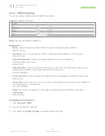
Page 76: ...l from the drop down OPTIONS MD5 SHA None Default MD5 Authorized Key Enter an authentication key This key acts as an electronic signature to authenticate an SNMPv3 message RANGE 8 32 Characters Default 12345678 Privacy Protocol Select the desired protocol from the drop down OPTIONS DES None Default DES Privacy Key Enter a Privacy Key This acts as an encryption for the data within a SNMPv3 message ...

Page 77: ...eceived within the set duration the device will be considered off line and a new STP route will be configured RANGE 6 40 seconds Default 20 seconds Forward Delay Enter a value for Forward Delay This setting will determine the length of time the access point will take to listen to the network and either retain current topology or generate a new topology based upon network switch and bridge status R...

Page 78: ...te settings and information for the 2 4GHz channel The 300 500 700 Series will indicate settings and information for the 2 4GHz and 5GHz channels VLAN Isolation Select Yes to assign a VLAN ID Default Not selected SSID Indicates the network name of the VLAN being tagged Any Wireless VLANs that need to be tagged should be added in the Wireless Settings page under Wireless Networks If a Wireless VLAN...

Page 79: ... router to handle guest client addresses on all the WAPs which gives Fast Roaming to all guest network clients Setup Requirements Multiple WAPs with fast roaming required for Guest Network SSID Router with VLAN support Araknis AN 300 RT 4L2W used for example Managed Switch Araknis AN 310 SW R 8 POE used for example Step 1 Configure the WAPs repeat for all 1 Log in as an Administrator 1 In the Wire...

Page 80: ...e the settings for the VLAN A VLAN ID Enter the same ID number for the guest VLAN as used in the WAPs B Name Enter a name for the guest network VLAN C Access Port Trunk Port Click one of the fields to open the selection box Since the WAPs tag packets for both VLAN 1 and 2 you must configure each port on the switch with a connected WAP as a trunk port for VLAN 2 The port connecting the switch to th...

Page 81: ...o guests don t get access to the rest of the network D Device Management Select Disabled so that guest clients can t access the router management interface E Route Binding Set whether routes use the WAN1 or WAN2 port Leave set to none for link failover F LAN1 2 3 4 Set all LAN ports to Tagged using the dropdowns 4 Click Apply to save the settings Configuration is complete Step 3 Test the Guest Net...

Page 82: ...ty to the AN 100 300 a hardware reset may be performed to reload the original base configuration file saved in the access point s memory Figure 70 Reset Button Reset Button Configuration Instructions 1 Using a paper clip or other small blunt tool press the reset button located on the top of the access point for 30 seconds 2 After two to four minutes the WAP will reboot Restart the setup process or...

Page 83: ...stem Information Table 23 Figure 17 Wireless Information 24 Figure 18 LAN Information and System Log 25 Figure 19 Radio Status 26 Figure 20 Utilization of SSID Status 27 Figure 21 Wireless Network Status 27 Figure 22 Connected Client Status 28 Figure 23 System Information 29 Figure 24 Date and Time Settings 30 Figure 25 Time Zone 31 Figure 26 IP Settings 32 Figure 27 Interface Settings 33 Figure 2...

Page 84: ...igure 50 Restore Factory Defaults 58 Figure 51 Firmware 59 Figure 52 Restart 60 Figure 53 Logout Alert 61 Figure 54 Radio Settings 62 Figure 55 Client Limit Settings 63 Figure 56 MAC Filter Settings 64 Figure 57 MAC Filter List 65 Figure 58 WPS Settings Menu 66 Figure 59 Site Survey 69 Figure 60 Spectrum Analyzer Settings 70 Figure 61 Spectrum Analyzer Usage View 71 Figure 62 Spectrum Analyzer Wav...

Page 85: ...ansmit Power See MCS table Receiver Sensitivity See MCS table 802 11n 2x2 2 MIMO PHY Data Rate Up to 300 Mbps Up to 300 Mbps in both frequency bands Operating Frequencies 2 4GHz 2 4GHz 5GHz Channel Bonding Yes 20MHz and 40MHz Memory 64MB 128MB Flash Memory 16MB 16MB Wireless Features Auto Channel Selection Yes Operation Modes Access Point Multiple SSIDs Yes up to 8 Wireless Security WPA2 PSK AES T...

Page 86: ...m Log Yes Bonjour Yes Araknis EZ Access Yes UPnP Yes Remote Config File Download Upload Yes OvrC Cloud Services Yes Wi Fi Scheduler Yes Site Survey Yes LED Control Yes Auto Reboot Yes Environmental Physical Dimensions W H D 6 9 x 6 9 x 1 3 External Power Supply 12V 1A DC 12V 2A DC Temperature Range Operating 32º to 122ºF 0 to 50ºC Storage 4Fº to 140ºF 20ºC to 60ºC Humidity Operating 90 or less Sto...

Page 87: ...1 Mbps 29 90 802 11g 2 4 GHz 6 Mbps 28 89 54 Mbps 25 71 802 11n HT20 2 4 GHz MCS 0 8 27 87 MCS 7 15 24 69 802 11n HT40 2 4GHz MCS 0 8 27 87 MCS 7 15 24 69 AN 300 AP I N 802 11a 5GHz 6 Mbps 26 90 54 Mbps 23 72 802 11b 2 4 GHz 1 Mbps 29 99 11 Mbps 29 93 802 11g 2 4 GHz 6 Mbps 29 96 54 Mbps 23 82 802 11n HT20 2 4 GHz MCS 0 8 29 97 MCS 7 15 23 78 802 11n HT40 2 4GHz MCS 0 8 29 86 MCS 7 15 23 69 802 11...

Page 88: ...le 802 11n 2x2 2 MIMO 3x3 3 MIMO PHY Data Rate Up to 300Mbps 2 4GHz Up to 867Mbps 5GHz Up to 450Mbps 2 4GHz Up to 1300Mbps 5GHz Operating Frequencies 2 4GHz 5GHz Channel Bonding Yes 20MHz 40MHz and 80MHz Max TX Power 28dBm 2 4GHz 26dBm 5GHz Memory 64MB 128MB Flash Memory 16MB 16MB Wireless Features Auto Channel Selection Yes Operation Modes Access Point Repeater Multiple SSIDs Yes up to 8 per radi...

Page 89: ...Log Yes Bonjour Yes Araknis EZ Access Yes UPnP Yes Remote Config File Download Upload Yes OvrC Cloud Services Yes Wi Fi Scheduler Yes Site Survey Yes LED Control Yes Auto Reboot Yes Environmental Physical Dimensions W H D 6 9 x 6 9 x 1 3 6 9 x 6 9 x 1 6 External Power Supply 12V 2A DC Temperature Range Operating 32º to 122ºF 0 to 50ºC Storage 4Fº to 140ºF 20ºC to 60ºC Humidity Operating 90 or less...

Page 90: ...6 802 11n HT20 2 4 GHz MCS 0 8 16 26 92 MCS 7 15 23 23 73 802 11n HT40 2 4 GHz MCS 0 8 16 26 88 MCS 7 15 23 23 72 802 11n HT20 5 GHz MCS 0 8 16 25 92 MCS 7 15 23 22 73 802 11n HT40 5 GHz MCS 0 8 16 24 88 MCS 7 15 23 21 72 802 11ac VHT20 5 GHz MCS 0_1SS 2SS 3SS 25 92 MCS 8_1SS 2SS 3SS 21 69 802 11ac VHT40 5 GHz MCS 0_1SS 2SS 3SS 24 88 MCS 9_1SS 2SS 3SS 20 64 802 11ac VHT80 5 GHz MCS 0_1SS 2SS 3SS 2...

Page 91: ...6 802 11n HT20 2 4 GHz MCS 0 8 16 26 92 MCS 7 15 23 23 73 802 11n HT40 2 4 GHz MCS 0 8 16 26 88 MCS 7 15 23 23 72 802 11n HT20 5 GHz MCS 0 8 16 25 92 MCS 7 15 23 22 73 802 11n HT40 5 GHz MCS 0 8 16 24 88 MCS 7 15 23 21 72 802 11ac VHT20 5 GHz MCS 0_1SS 2SS 3SS 25 92 MCS 8_1SS 2SS 3SS 21 69 802 11ac VHT40 5 GHz MCS 0_1SS 2SS 3SS 24 88 MCS 9_1SS 2SS 3SS 20 64 802 11ac VHT80 5 GHz MCS 0_1SS 2SS 3SS 2...

Page 92: ...ing antenna Increase the separation between the equipment and receiver Connect the equipment into an outlet on a circuit different from that to which the receiver is connected Consult the dealer or an experienced radio TV technician for help FCC Caution Any changes or modifications not expressly approved by the party responsible for compliance could void the user s authority to operate this equipm...

Page 93: ... R TTE Directive EN 301 489 1 Electromagnetic compatibility and Radio Spectrum Matters ERM ElectroMagnetic Compatibility EMC standard for radio equipment and services Part 1 Common technical requirements EN 301 489 17 Electromagnetic compatibility and Radio spectrum Matters ERM ElectroMagnetic Compatibility EMC standard for radio equipment and services Part 17 Specific conditions for 2 4 GHz wideb...

Page 94: ...point in overeenstemming is met de essentiële eisen en de andere relevante bepalingen van richtlijn 1999 5 EG Malti Maltese Hawnhekk Araknis Networks jiddikjara li dan wireless access point jikkonforma mal ħtiġijiet essenzjali u ma provvedimenti oħrajn relevanti li hemm fid Dirrettiva 1999 5 EC Magyar Hungarian Alulírott Araknis Networks nyilatkozom hogy a wireless access point megfelel a vonatkoz...

Page 95: ...bject to the following two conditions 1 This device may not cause harmful interference and 2 this device must accept any interference received including interference that may cause undesired operation This transmitter must not be co located or operating in conjunction with any other antenna or transmitter Operations in the 5 15 5 25GHz band are restricted to indoor usage only IMPORTANT NOTE FCC Ra...

Page 96: ...ps Europe EU Declaration of Conformity This device complies with the essential requirements of the R TTE Directive 1999 5 EC The following test methods have been applied in order to prove presumption of conformity with the essential requirements of the R TTE Directive 1999 5 EC EN60950 1 Safety of Information Technology Equipment EN50385 Generic standard to demonstrate the compliance of electronic...

Page 97: ...raknis Networks seadme wireless access point vastavust direktiivi 1999 5 EÜ põhinõuetele ja nimetatud direktiivist tulenevatele teistele asjakohastele sätetele English Hereby Araknis Networks declares that this wireless access point is in compliance with the essential requirements and other relevant provisions of Directive 1999 5 EC Español Spanish Por medio de la presente Araknis Networks declara...

Page 98: ...guês Portuguese Araknis Networks declara que este wireless access point está conforme com os requisitos essenciais e outras disposições da Directiva 1999 5 CE Slovensko Slovenian Araknis Networks izjavlja da je ta wireless access point v skladu z bistvenimi zahtevami in ostalimi relevantnimi določili direktive 1999 5 ES Slovensky Slovak Araknis Networks týmto vyhlasuje že wireless access point spĺ...

Page 99: ...repairs on all components found to be defective in material or workmanship under normal conditions of use This warranty shall not apply to products that have been abused modified or disassembled Products to be repaired under this warranty must be returned to SnapAV or a designated service center with prior notification and an assigned return authorization number RA Contacting Technical Support P 8...

Page 100: ... 2016 Araknis Networks 160524 1600 ...

Reviews: