166
Options List
C.17
Option 29: Four Additional Outputs; Dry Contacts; +25/50
Vdc
C.17.1
General Description
This document describes Option 29: Four Additional Outputs With Dry Contact and +25/50
VDC; which may be used in the Arbiter Systems Models 1084A/B/C, 1088B, and 1093A/B/C
GPS Satellite-Controlled Clocks. Option 29 includes six configurable outputs. Four are standard,
5 V CMOS outputs; two are Aromat AQV210E solid-state relays (SSRs). A +25 or +50 VDC
supply is available on-board and may be switched by the SSR outputs.
C.17.2
Specifications
General
Connector
16-position, 5 mm Pluggable Terminal Strip. Four 2-position
and two 4-position mating connectors provided. The connec-
tors accept wire sizes of 0.25 to 2.5 mm
2
(AWG 12 to 22).
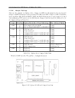
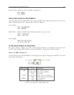
See Table C.12 and Figure C.20 for Connector Configuration.
Digital Outputs
Quantity
4
Type:
5 V CMOS, individually configurable
Rating:
+5 V open-circuit, nominal
75 mA peak current, per channel
+3.5 V typical at 75 mA peak current
Available Signals:
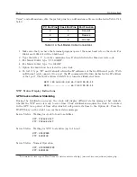
Jumper selectable to any of the digital signals available from
the clock mainframe plus on board generation of 1 PPM and
1 PPH for the 1093 clock models. See Figure C.19 for Jumper
location and selections.
Solid State Relay Output
Quantity:
2
Type:
Aromat AQV210E solid-state relays, 130 mA AC or DC at
350 V peak.
Rating:
Limited to 100 mA DC, 140 Vrms / 180 V peak by the fuse
and surge suppression devices.
Timing:
Propagation Delay, 90
µ
s Nominal, to 50%.
Rise Time, 50
µ
s Nominal, 20-80%.
Summary of Contents for 1084A
Page 4: ...iv ...
Page 6: ...vi ...
Page 18: ...xviii LIST OF FIGURES ...
Page 24: ...4 Unpacking the Clock ...
Page 36: ...16 Connecting Inlet Power Input and Output Signals ...
Page 44: ...24 GPS Antenna and Cable Information ...
Page 114: ...94 Startup and Basic Operation ...
Page 123: ...B 4 Physical Dimensions 103 Figure B 1 Suggested Mounting of the AS0094500 Surge Arrester ...
Page 124: ...104 Using Surge Arresters ...
Page 134: ...114 Options List C 6 2 Option 06 Firmware Setup Figure C 3 Option 06 Firmware Setup ...
Page 142: ...122 Options List Figure C 5 Option 06 Output Jumper Settings ...
Page 158: ...138 Options List Figure C 13 Option 17 Board Layout and Jumper Locations ...
Page 163: ...C 13 Option 20A Four Fiber Optic Outputs 143 Figure C 14 Option 20A Jumper Locations ...
Page 170: ...150 Options List Figure C 16 Option 23 Internal Jumper Setup ...
Page 172: ...152 Options List Figure C 17 Option 27 Jumper Locations ...
Page 190: ...170 Options List Figure C 20 Option 29 Connector Signal Locations ...
Page 246: ...226 Options List ...


