168
Options List
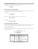
Pin
Function
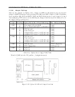
Setup Jumpers–Default Settings
1 (Rightmost)
CMOS Output 1
JMP4: Signal Select Default = 1 PPH
2
Ground
–
3
CMOS Output 2
JMP3: Signal Select Default = 1 PPM
4
Ground
–
5
CMOS Output 3
JMP2: Signal Select Default = Prog. Pulse
6
Ground
–
7
CMOS Output 4
JMP1: Signal Select Default = IRIG-B
8
Ground
–
9
Ground
–
10
SSR Output 1
JMP5: Signal Select Default = 1 PPM
11
SSR Output 1
JMP7: Standard/50ms Default = 50 ms
12
+25/50 VDC 1
JMP10: +25/50 VDC Default = 50 VDC
13
Ground
–
14
SSR Output 2
JMP6: Signal Select Default = 1 PPM
15
SSR Output 2
JMP8: Standard/50 ms Default = 50ms
16 (Leftmost)
+25/50 VDC 2
JMP11: +25/50 VDC Default = 50 VDC
Table C.12: Option 29, Output Connectors and Setup Jumpers
C.17.3
Firmware Configuration
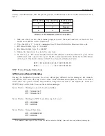
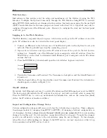
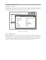
1. It is necessary to verify the configuration in the Option Setup Menu so Option 29 is recognized.
2. Apply power and observe the front panel display; when it displays “CLOCK STATUS
STARTUP,” press the SETUP key.
3. Press the SETUP key until SET OPTION CONTROL? appears.
4. Press ENTER twice so that “AUX. BOARD OPTION” appears. Press the UP key so that
the option number indicates “29” and press ENTER.
5. Press any of the upper row of keys to exit the setup menus.
Summary of Contents for 1084A
Page 4: ...iv ...
Page 6: ...vi ...
Page 18: ...xviii LIST OF FIGURES ...
Page 24: ...4 Unpacking the Clock ...
Page 36: ...16 Connecting Inlet Power Input and Output Signals ...
Page 44: ...24 GPS Antenna and Cable Information ...
Page 114: ...94 Startup and Basic Operation ...
Page 123: ...B 4 Physical Dimensions 103 Figure B 1 Suggested Mounting of the AS0094500 Surge Arrester ...
Page 124: ...104 Using Surge Arresters ...
Page 134: ...114 Options List C 6 2 Option 06 Firmware Setup Figure C 3 Option 06 Firmware Setup ...
Page 142: ...122 Options List Figure C 5 Option 06 Output Jumper Settings ...
Page 158: ...138 Options List Figure C 13 Option 17 Board Layout and Jumper Locations ...
Page 163: ...C 13 Option 20A Four Fiber Optic Outputs 143 Figure C 14 Option 20A Jumper Locations ...
Page 170: ...150 Options List Figure C 16 Option 23 Internal Jumper Setup ...
Page 172: ...152 Options List Figure C 17 Option 27 Jumper Locations ...
Page 190: ...170 Options List Figure C 20 Option 29 Connector Signal Locations ...
Page 246: ...226 Options List ...


