182
Options List
Web Interface
Instructions in this section cover the setup and maintenance of the Option 34 using the Web
Interface. Configure the Option 34 insecurely through the Web Interface using HTTP, or securely
using HTTPS. Both methods are discussed in this section. Instructions on using the Secure Shell
(SSH) Console Interface for the same purpose are found in Section C.19.3. Option 34 may only be
configured through one of the Ethernet ports. However, to configure the clock use the front panel
or RS-232 port.
Logging in to the Web Interface
The Web Interface responds when you open a web browser and type in the IP address of one of its
ports. IP address may also be viewed in the front panel display.
1. Connect an Ethernet cable between one of the Ethernet ports on the Option 34 and your
network. This step should speed up the connecting process.
2. Open your web browser and type in the IP address of one of the ports in the web browser
address bar. Normally, one of the Ethernet ports is assigned a static IP address. Press the
STATUS key on the clock to determine which Ethernet port is assigned a static IP address
and use that one.
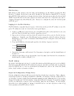
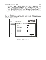
3. Press the ENTER key, which should open the web interface login as seen below.
Username
Password
Login
4. Type in the Username and Password. The Username is clockoption, and the default Password
is password.
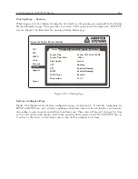
5. Click the Login button. If you typed in the correct Username and Password, the web interface
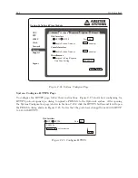
should appear as shown in Figure C.23.
The IP Address
By default, Net1 Ethernet port is set to a static IP address and Net2 Ethernet port is set for DHCP.
The front panel will indicate the IP address of each port provided a network cable is connected.
Press the SETUP key to view any network-related information, such as the connection (Link)
status, the IP address or hardware address.
Important Configuration Change Notes
Certain configuration changes will cause you to lose the web interface connection. These configura-
tion changes include (1) changing from HTTP to HTTPS, (2) changing a Network configuration, or
(3) changing a System configuration
on the port which you are connected
. If you are making
changes to another port, the web interface connection will not be dropped. To make the changes
persist, you will need to re-log in to the web interface using the new setting(s). To lose changes,
reboot the clock. After making any changes to the NTP service, you may experience a delay of up
to five minutes for the NTP service to start.
Summary of Contents for 1084A
Page 4: ...iv ...
Page 6: ...vi ...
Page 18: ...xviii LIST OF FIGURES ...
Page 24: ...4 Unpacking the Clock ...
Page 36: ...16 Connecting Inlet Power Input and Output Signals ...
Page 44: ...24 GPS Antenna and Cable Information ...
Page 114: ...94 Startup and Basic Operation ...
Page 123: ...B 4 Physical Dimensions 103 Figure B 1 Suggested Mounting of the AS0094500 Surge Arrester ...
Page 124: ...104 Using Surge Arresters ...
Page 134: ...114 Options List C 6 2 Option 06 Firmware Setup Figure C 3 Option 06 Firmware Setup ...
Page 142: ...122 Options List Figure C 5 Option 06 Output Jumper Settings ...
Page 158: ...138 Options List Figure C 13 Option 17 Board Layout and Jumper Locations ...
Page 163: ...C 13 Option 20A Four Fiber Optic Outputs 143 Figure C 14 Option 20A Jumper Locations ...
Page 170: ...150 Options List Figure C 16 Option 23 Internal Jumper Setup ...
Page 172: ...152 Options List Figure C 17 Option 27 Jumper Locations ...
Page 190: ...170 Options List Figure C 20 Option 29 Connector Signal Locations ...
Page 246: ...226 Options List ...


