164
Options List
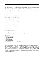
Start Broadcast Mode–ASCII
Command:
B7, O7
“B7” configures the
Standard RS-232
broadcast mode to send Time, Frequency, and Phase Devi-
ation, once per second, in ASCII format. “O7” configures the
Option RS-232
broadcast mode to
send Time, Frequency and Phase Deviation, once per second, in ASCII format.
Response:
broadcast mode, UTC:
mm/dd/yyyy hh:mm:ssU ss +f.fff +t.tttt ppp.ppp vvv.vv
C
broadcast mode, Local:
mm/dd/yyyy hh:mm:ssL ss +f.fff +t.tttt ppp.ppp vvv.vv
C
Where:
mm/dd/yyyy
= Date
hh:mm:ssU
= Time of Day, UTC
(or)
hh:mm:ssL
= Time of Day, Local
ss
= Status
first character is Reference Status:
0 : Locked;
1 : Unlocked;
second character is clock status per IEEE 1344
+f.fff
signed Frequency Error in Hz.
+t.tttt
signed Time Deviation in seconds.
ppp.pp
Phase Angle, 0 to 360 degrees.
vvv.vv
Line voltage, rms Volts.
Set Measured System Deviation
Command:
(-)s.fsRD
“(-)s.fsRD” sets the system deviation.
Response:
C
Where:
s = 0 to
±
2000 seconds
fs = fractional seconds
Set Phase Calibration
Command:
p:kPC
“p:kPC” sets the phase calibration offset. Phase offset is stored in protected RAM.
Response:
C
Where:
p = Phase Offset in degrees
k = Security Key (e.g. 1084)
Summary of Contents for 1084A
Page 4: ...iv ...
Page 6: ...vi ...
Page 18: ...xviii LIST OF FIGURES ...
Page 24: ...4 Unpacking the Clock ...
Page 36: ...16 Connecting Inlet Power Input and Output Signals ...
Page 44: ...24 GPS Antenna and Cable Information ...
Page 114: ...94 Startup and Basic Operation ...
Page 123: ...B 4 Physical Dimensions 103 Figure B 1 Suggested Mounting of the AS0094500 Surge Arrester ...
Page 124: ...104 Using Surge Arresters ...
Page 134: ...114 Options List C 6 2 Option 06 Firmware Setup Figure C 3 Option 06 Firmware Setup ...
Page 142: ...122 Options List Figure C 5 Option 06 Output Jumper Settings ...
Page 158: ...138 Options List Figure C 13 Option 17 Board Layout and Jumper Locations ...
Page 163: ...C 13 Option 20A Four Fiber Optic Outputs 143 Figure C 14 Option 20A Jumper Locations ...
Page 170: ...150 Options List Figure C 16 Option 23 Internal Jumper Setup ...
Page 172: ...152 Options List Figure C 17 Option 27 Jumper Locations ...
Page 190: ...170 Options List Figure C 20 Option 29 Connector Signal Locations ...
Page 246: ...226 Options List ...


