C.19 Option 34: NTP/PTP Server
185
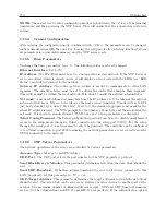
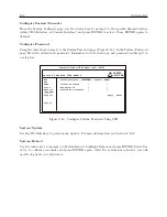
System Configure Password
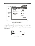
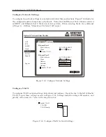
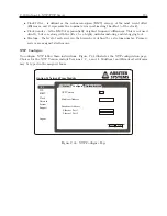
To configure the system password follow these instructions. From Figure C.24, select the Password
tab. Figure C.26 shows where to configure the System password. In the System page, click the
Password tab and fill in the old and new password. Click the Apply button. Remember to write
down any new password and keep it in a safe place.
Apply
Reset
Current Password
New Password
Confirm New Password
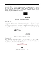
Figure C.26: Configure System Password
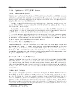
System Update
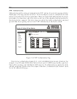
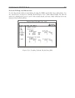
To update any Option 34 firmware package follow these instructions. From Figure C.24, select
the Update tab and click the Choose File button shown in Figure C.27. This should open your
file browser in which you should be able to locate the file package obtained from Arbiter Systems.
Click the Update button and the file should load to the Option 34. After uploading the package
the Option 34 must be rebooted for the changes to take effect.
Upload
Reset
Upload Package File
Choose File
no file selected
Figure C.27: Update System Firmware Package
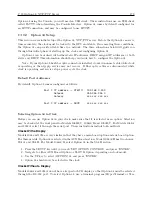
System Reboot
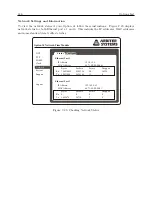
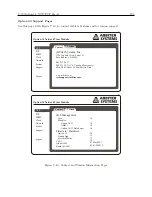
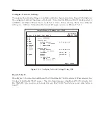
To reboot the Option 34 follow these instructions. From Figure C.24 select the Reboot tab. Fig-
ure C.28 shows only one button to click to reboot the system. Be aware that rebooting the system
will disconnect all active sesstions with the Option 34.
Reboot
WARNING:
Rebooting the system will disconnect all
active sessions (including this one).
Figure C.28: Rebooting the System
Summary of Contents for 1084A
Page 4: ...iv ...
Page 6: ...vi ...
Page 18: ...xviii LIST OF FIGURES ...
Page 24: ...4 Unpacking the Clock ...
Page 36: ...16 Connecting Inlet Power Input and Output Signals ...
Page 44: ...24 GPS Antenna and Cable Information ...
Page 114: ...94 Startup and Basic Operation ...
Page 123: ...B 4 Physical Dimensions 103 Figure B 1 Suggested Mounting of the AS0094500 Surge Arrester ...
Page 124: ...104 Using Surge Arresters ...
Page 134: ...114 Options List C 6 2 Option 06 Firmware Setup Figure C 3 Option 06 Firmware Setup ...
Page 142: ...122 Options List Figure C 5 Option 06 Output Jumper Settings ...
Page 158: ...138 Options List Figure C 13 Option 17 Board Layout and Jumper Locations ...
Page 163: ...C 13 Option 20A Four Fiber Optic Outputs 143 Figure C 14 Option 20A Jumper Locations ...
Page 170: ...150 Options List Figure C 16 Option 23 Internal Jumper Setup ...
Page 172: ...152 Options List Figure C 17 Option 27 Jumper Locations ...
Page 190: ...170 Options List Figure C 20 Option 29 Connector Signal Locations ...
Page 246: ...226 Options List ...

