192
Options List
•
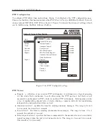
Peer Delay Request – allows the requesting device to calculate the propagation delay for the
individual segment.
•
Announce receipt timeout – specifies the number of announceInterval that has to pass
without receipt of an Announce message before the occurrence of the event AN-
NOUNCE RECEIPT TIMEOUT EXPIRE.
•
Delay mechanism – communication delay, end to end or peer to peer.
•
Protocol – UDP IPv4, UDP IPv6 or Layer2.
•
Clock class value – used to advertise the quality level of the clock. A GPS clock is given the
value of 6.
•
Clock accuracy – 22 is used for clock accuracy to within 250 ns.
•
Priority 1 – used in the execution of the best master clock algorithm.
•
Priority 2 – used in the execution of the best master clock algorithm.
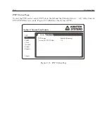
NTP Status Page
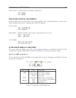
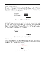
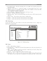
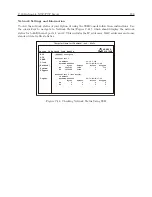
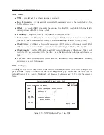
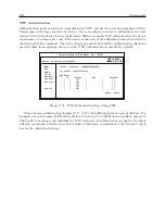
To view the NTP service, select NTP tab on the left and the Status tab above. Figure C.37
illustrates the status of NTP.
Option 34 Network Time Module
Status
Configure
NTP
PTP
SNMP
Clock
Network
System
Support
Logout
Authentication
NTP
Root Dispersion
Offset
Frequency
System Jitter
Clock Jitter
Clock wander
Stratum
Running
0.420
-0.063
1.337
0.009
0.008
0.001
1
Figure C.37: NTP Status Page
NTP Terms
•
NTP – either running or stopped.
•
Root Dispersion – (or dispersion) represents the maximum error of the local clock relative to
the reference clock.
•
Offset – (or clock offset) represents the amount to adjust the local clock to bring it into
correspondence with the reference clock.
•
Frequency – frequency offset (PPM) relative to hardware clock.
•
System Jitter (psi) – is defined as the root-mean-square (RMS) average of the most recent
offset differences, and it represents the nominal error in estimating the offset (of the system).
Summary of Contents for 1084A
Page 4: ...iv ...
Page 6: ...vi ...
Page 18: ...xviii LIST OF FIGURES ...
Page 24: ...4 Unpacking the Clock ...
Page 36: ...16 Connecting Inlet Power Input and Output Signals ...
Page 44: ...24 GPS Antenna and Cable Information ...
Page 114: ...94 Startup and Basic Operation ...
Page 123: ...B 4 Physical Dimensions 103 Figure B 1 Suggested Mounting of the AS0094500 Surge Arrester ...
Page 124: ...104 Using Surge Arresters ...
Page 134: ...114 Options List C 6 2 Option 06 Firmware Setup Figure C 3 Option 06 Firmware Setup ...
Page 142: ...122 Options List Figure C 5 Option 06 Output Jumper Settings ...
Page 158: ...138 Options List Figure C 13 Option 17 Board Layout and Jumper Locations ...
Page 163: ...C 13 Option 20A Four Fiber Optic Outputs 143 Figure C 14 Option 20A Jumper Locations ...
Page 170: ...150 Options List Figure C 16 Option 23 Internal Jumper Setup ...
Page 172: ...152 Options List Figure C 17 Option 27 Jumper Locations ...
Page 190: ...170 Options List Figure C 20 Option 29 Connector Signal Locations ...
Page 246: ...226 Options List ...

