222
Options List
C.20
Option 36: Four Configurable Outputs
C.20.1
General Description
Option 36 replaces Option 03 and adds four rear-panel outputs, which may be configured to any
available signal in the 1084A/B/C series clocks. The configuration of the four outputs can be
changed at any time via internal jumper settings.
C.20.2
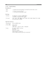
Specifications
General
Output Connectors:
BNC-type RF connectors (4).
Analog Outputs
Output Type
Operational amplifier (LF353) output, with 557-ohm series resistor.
Available Outputs:
Modulated IRIG-B.
Signal characteristics:
IRIG-B time code, modulated onto 1 kHz 4.5 Vpp sine wave carrier.
Digital Outputs
Output Type:
High-Speed CMOS (74HC126), 0 to 5 volts, with 47 ohm
series resistance.
Available Outputs:
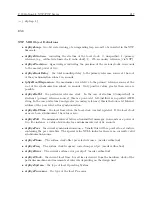
Note: Available on Model 1084A/B/C are shown in Ta-
ble C.16
IRIG-B:
IRIG format B time code (unmodulated).
C.20.3
Changing Outputs via Internal Settings
Case Removal
To change the configuration of Option 36, the top cover of the instrument must be removed. Turn
off the instrument, and disconnect the power cord. Using a T-25 Torx driver, remove the four
screws holding the cover (and rack mount ears, if used) in place, and lift the cover off.
WARNING
Do not remove the top cover while power is applied. Hazardous voltages are present
while the power cord is connected. Always disconnect the unit from the input power source before
removal of the top cover.
General Information
Option 36 incorporates a flexible output selection system using jumpers on the Option 36 printed
circuit board. Each of the four rear-panel BNC-type I/O connectors, included with Option 36, can
Summary of Contents for 1084A
Page 4: ...iv ...
Page 6: ...vi ...
Page 18: ...xviii LIST OF FIGURES ...
Page 24: ...4 Unpacking the Clock ...
Page 36: ...16 Connecting Inlet Power Input and Output Signals ...
Page 44: ...24 GPS Antenna and Cable Information ...
Page 114: ...94 Startup and Basic Operation ...
Page 123: ...B 4 Physical Dimensions 103 Figure B 1 Suggested Mounting of the AS0094500 Surge Arrester ...
Page 124: ...104 Using Surge Arresters ...
Page 134: ...114 Options List C 6 2 Option 06 Firmware Setup Figure C 3 Option 06 Firmware Setup ...
Page 142: ...122 Options List Figure C 5 Option 06 Output Jumper Settings ...
Page 158: ...138 Options List Figure C 13 Option 17 Board Layout and Jumper Locations ...
Page 163: ...C 13 Option 20A Four Fiber Optic Outputs 143 Figure C 14 Option 20A Jumper Locations ...
Page 170: ...150 Options List Figure C 16 Option 23 Internal Jumper Setup ...
Page 172: ...152 Options List Figure C 17 Option 27 Jumper Locations ...
Page 190: ...170 Options List Figure C 20 Option 29 Connector Signal Locations ...
Page 246: ...226 Options List ...

