2.3 Rear Panel Identification and Connectors
9
2.3.1
Power Inlet
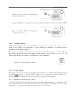
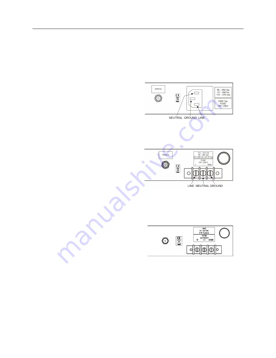
To cover all of the possible inlet power conditions, the Model 1088B has three optional power
supplies. Please examine the paperwork you received, to make sure you have correctly identified
the inlet connection. Supply types are listed below:
•
Standard, IEC-320 supply with a range of 85 to 264 Vac, 47 to 440 Hz and 110 to 370 Vdc
Figure 2.3: Standard Power Supply
•
Option 07, Terminal Power Strip with a range of 85 to 264 Vac, 47 to 440 Hz and 110 to 370
Vdc
Figure 2.4: Option 07 Power Supply, Termi-
nal Power Strip Connector
•
Option 08, 10 to 60 Vdc ONLY, Terminal Power Strip.
BE SURE TO OBSERVE COR-
RECT POLARITY
, as the power supply used with Option 08 will not accept reverse input
polarity.
Figure 2.5: Option 08 Power Supply Termi-
nal Strip Connector
•
Option 15A, 125 Vdc Terminal Power Strip with Surge Withstand Protect Circuitry (SWC)
Summary of Contents for 1088A
Page 4: ...iv ...
Page 6: ...vi ...
Page 18: ...xviii LIST OF FIGURES ...
Page 23: ...1 4 Attaching Rack Mount Ears to 1088A B Series Clocks 3 Figure 1 2 Attaching Rack Mount Ears ...
Page 24: ...4 Unpacking the Clock ...
Page 32: ...12 Front and Rear Panels ...
Page 38: ...18 Connecting Inlet Power Input and Output Signals ...
Page 46: ...26 GPS Antenna and Cable Information ...
Page 48: ...28 Setting Internal Jumpers Figure 5 1 Model 1088B Main Board ...
Page 76: ...56 The Setup Menus ...
Page 112: ...92 Serial Communication and Command Set ...
Page 127: ...B 4 Physical Dimensions 107 Figure B 1 Suggested Mounting of the AS0094500 Surge Arrester ...
Page 128: ...108 Using Surge Arresters ...
Page 145: ...C 5 Option 04 Parallel BCD Output 125 Figure C 4 Option 04 Output Jumper Settings ...
Page 146: ...126 Options List Figure C 5 Option 04 Board Layout and Jumper Locations ...
Page 166: ...146 Options List Figure C 12 Option 17 Board Layout and Jumper Locations ...
Page 187: ...C 16 Option 20A Four Fiber Optic Outputs 167 Figure C 22 Option 20A Jumper Locations ...
Page 194: ...174 Options List Figure C 24 Option 23 Internal Jumper Setup ...
Page 196: ...176 Options List Figure C 25 Option 27 Jumper Locations ...
Page 214: ...194 Options List Figure C 28 Option 29 Connector Signal Locations ...
Page 270: ...250 Options List ...


