5.2 Changing Hardware Settings Via Internal Jumpers
29
5.2.1
Cover Removal
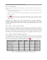
To change jumper configurations, the instrument cover must be removed. Remove top cover as
follows:
1. On all Models disconnect the power cord. If equipped with Option 04 (power switch), first
turn the power switch to OFF.
2. Using a T-25 driver, remove the four screws securing the cover (and rack-mount ears, if used).
3. Lift the cover off.
4. Figure 5.1 illustrates the main board and locates all the jumpers. Also, a label located on the
inside of the top cover provides a quick reference for the I/O functions and their respective
jumper settings.
Warning
DO NOT REMOVE TOP COVER WHILE POWER IS APPLIED. HAZARDOUS
VOLTAGES ARE PRESENT WHILE THE POWER CORD IS CONNECTED. ALWAYS DIS-
CONNECT THE UNIT FROM THE INPUT POWER SOURCE BEFORE REMOVAL OF THE
TOP COVER.
5.2.2
JMP1
−
Event A and B Selection
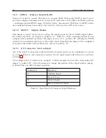
The Model 1088B has the capability to provide for two possible event inputs: Event A and Event B.
Jumper 1 selects the port to which the Event A signal is applied, either the standard I/O connector
(J4) or the main RS-232 port. Position A selects the standard I/O and position B selects the main
RS-232 port. Event B input is always applied to J3. Event A and Event B alternatively provide
for 1 PPS deviation measurements. These measurements are continuously updated each second.
5.2.3
JMP2
−
Frequency Reference Selection
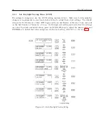
The Model 1088B is able to use an external timing reference instead of the internal clock signal.
Usable signals are 100 kHz, 1 MHz, 5 MHz and 10 MHz. For external reference operation set JMP2
to position B and select the External Reference Input Frequency with JMP3. Acceptable signal
levels for an external reference are 5-volt TTL/CMOS. See Table 5.1
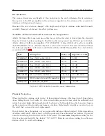
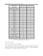
Reference Frequency
JMP2
JMP3
JMP15
Source
Internal Standard
A*
X
A,C
Internal
Option 12A
B
B
A,C
Internal
External 10 MHz
B
A
B
External
External 5 MHz
B
B
B
External
External 1 MHz
B
C
B
External
External 100 kHz
B
D
B
External
Table 5.1: External Reference Input Frequency Settings (JMP3)
Summary of Contents for 1088A
Page 4: ...iv ...
Page 6: ...vi ...
Page 18: ...xviii LIST OF FIGURES ...
Page 23: ...1 4 Attaching Rack Mount Ears to 1088A B Series Clocks 3 Figure 1 2 Attaching Rack Mount Ears ...
Page 24: ...4 Unpacking the Clock ...
Page 32: ...12 Front and Rear Panels ...
Page 38: ...18 Connecting Inlet Power Input and Output Signals ...
Page 46: ...26 GPS Antenna and Cable Information ...
Page 48: ...28 Setting Internal Jumpers Figure 5 1 Model 1088B Main Board ...
Page 76: ...56 The Setup Menus ...
Page 112: ...92 Serial Communication and Command Set ...
Page 127: ...B 4 Physical Dimensions 107 Figure B 1 Suggested Mounting of the AS0094500 Surge Arrester ...
Page 128: ...108 Using Surge Arresters ...
Page 145: ...C 5 Option 04 Parallel BCD Output 125 Figure C 4 Option 04 Output Jumper Settings ...
Page 146: ...126 Options List Figure C 5 Option 04 Board Layout and Jumper Locations ...
Page 166: ...146 Options List Figure C 12 Option 17 Board Layout and Jumper Locations ...
Page 187: ...C 16 Option 20A Four Fiber Optic Outputs 167 Figure C 22 Option 20A Jumper Locations ...
Page 194: ...174 Options List Figure C 24 Option 23 Internal Jumper Setup ...
Page 196: ...176 Options List Figure C 25 Option 27 Jumper Locations ...
Page 214: ...194 Options List Figure C 28 Option 29 Connector Signal Locations ...
Page 270: ...250 Options List ...


