32
Setting Internal Jumpers
5.2.9
JMP16
−
Battery Backed RAM
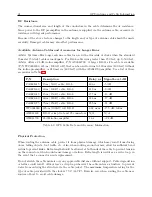
Jumper 16 is used to connect the battery to program RAM. This specific RAM is used to store
any user-configured information such as serial port preferences, local offsets and timing settings
−
anything found in SETUP menu. With the battery disconnected (JMP16 set to OFF), all the
user-configured information would be lost when the clock is powered off or loses power.
5.2.10
JMP17
−
Output Enable
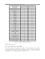
This jumper is used at the factory for setting the output enable for the 5V CMOS output buffers.
For normal operation, set jumper to position “A”. With two clocks containing Option 18 and
configured for redundant operation, this jumper may be set to position “B”, allowing the CMOS
outputs to be paralleled and driven by the on-line clock. Normally, this jumper will be configured
as required when delivered from the factory and set to position “A”.
5.2.11
I/O Connector Used as Input
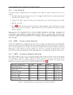
Any of the four I/O connectors included with the standard model can be reconfigured to operate
as an input. However, each connector is restricted to the input function listed for it as seen below
in Table 5.3.
To reconfigure any I/O connector as “an input”, all that is required is to set the corresponding I/O
jumper to position “B”. It is not necessary to change the position of the output function jumper,
as this will have no effect on input operation.
Connector
Function
J2
Auxiliary Input
J3
Event B Input
J4
Event A Input
J5
External Reference Input
Table 5.3: Rear Panel I/O Connector Input Functions
Summary of Contents for 1088A
Page 4: ...iv ...
Page 6: ...vi ...
Page 18: ...xviii LIST OF FIGURES ...
Page 23: ...1 4 Attaching Rack Mount Ears to 1088A B Series Clocks 3 Figure 1 2 Attaching Rack Mount Ears ...
Page 24: ...4 Unpacking the Clock ...
Page 32: ...12 Front and Rear Panels ...
Page 38: ...18 Connecting Inlet Power Input and Output Signals ...
Page 46: ...26 GPS Antenna and Cable Information ...
Page 48: ...28 Setting Internal Jumpers Figure 5 1 Model 1088B Main Board ...
Page 76: ...56 The Setup Menus ...
Page 112: ...92 Serial Communication and Command Set ...
Page 127: ...B 4 Physical Dimensions 107 Figure B 1 Suggested Mounting of the AS0094500 Surge Arrester ...
Page 128: ...108 Using Surge Arresters ...
Page 145: ...C 5 Option 04 Parallel BCD Output 125 Figure C 4 Option 04 Output Jumper Settings ...
Page 146: ...126 Options List Figure C 5 Option 04 Board Layout and Jumper Locations ...
Page 166: ...146 Options List Figure C 12 Option 17 Board Layout and Jumper Locations ...
Page 187: ...C 16 Option 20A Four Fiber Optic Outputs 167 Figure C 22 Option 20A Jumper Locations ...
Page 194: ...174 Options List Figure C 24 Option 23 Internal Jumper Setup ...
Page 196: ...176 Options List Figure C 25 Option 27 Jumper Locations ...
Page 214: ...194 Options List Figure C 28 Option 29 Connector Signal Locations ...
Page 270: ...250 Options List ...


