C.14 Option 18: IRIG-B BUS Distribution, Fault Monitor and 2nd RS-232 Port
153
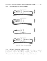
The Model 10882A tap is used to provide a decoupled, isolated output signal to your system loads.
The source impedance of this tap is approximately 600 ohms, and it will provide an open-circuit
signal level of 6.4 to 11 Vpp, depending on overall system loading and distance from the clock
mainframe. Each tap provides 3750 Vrms isolation from the distribution bus to the load, as well as
surge suppression and EMI filtering. The taps are capacitively-isolated from the dc bus monitoring
current.
One Model 10884A terminator is located at the end of a linear distribution bus, and one at the end
of each branch. This inductive terminator provides a high impedance to the IRIG-B signal while
providing a return path for the dc loop current used for continuity monitoring.
The Model 10883A splitter is used to drive a branch from the main distribution bus, or to split a
bus into two branches. It drives the two output branches in parallel as far as the IRIG-B signal is
concerned, while they are connected in series for the dc loop monitoring current.
Bus Configurations
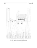
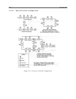
Using these three components, a linear or branched network can be assembled in any required
configuration, while maintaining the ability of the Option 18 bus monitor to detect an open-circuit
fault at any point along the bus or any branch. If the Model 10885A redundant-ring adapter is
used to build a basic ring network, the Model 10884A terminator and Model 10883A splitter are
not required. However, as shown in the accompanying figures, a complex system can be built using
rings, branches, and linear segments in various combinations as needed to satisfy your requirements.
Determining Actual Signal Output Levels
The actual signal levels at the outputs of the various taps may be approximated with acceptable
accuracy by treating the network as a resistive array. The source impedance of the Option 18
bus output is approximately 21 ohms. The recommended cable (Belden 8760 or equivalent, #18
AWG shielded twisted pair) has a resistance of 43 ohms per kilometer (13 ohms per thousand feet).
The Model 10885A redundant-ring adapter has an effective series resistance to the ac signal of
approximately 10 ohms. The Model 10883A splitter has an effective series resistance of less than
one ohm.
Each Model 10882A tap places a load across the bus of approximately 580 ohms plus the load
impedance it is driving; i.e. the tap acts like a 580-ohm resistor in series with the load, with which
it forms a voltage divider. The Model 10884A terminator may be treated as an open circuit so far
as the IRIG signal is concerned.
By using these numbers, along with the load impedances, in a suitable circuit-analysis program,
or by solving the loop equations manually, the attenuation from the Option 18 bus output to the
load at each tap may be determined. The open-circuit output level at the Option 18 bus output is
nominally 11 volts peak-to-peak with a tolerance of +5%; knowing this, along with the attenuation
values, you can calculate the signal level at each tap.
Total DC Resistance Limit - Bus Monitor
There is a 500-ohm limit on the total dc resistance of the distribution system to ensure proper
operation of the bus continuity monitor. This limit will not normally be a factor in system design.
Still, loop dc resistance should be calculated for each system.
Summary of Contents for 1088A
Page 4: ...iv ...
Page 6: ...vi ...
Page 18: ...xviii LIST OF FIGURES ...
Page 23: ...1 4 Attaching Rack Mount Ears to 1088A B Series Clocks 3 Figure 1 2 Attaching Rack Mount Ears ...
Page 24: ...4 Unpacking the Clock ...
Page 32: ...12 Front and Rear Panels ...
Page 38: ...18 Connecting Inlet Power Input and Output Signals ...
Page 46: ...26 GPS Antenna and Cable Information ...
Page 48: ...28 Setting Internal Jumpers Figure 5 1 Model 1088B Main Board ...
Page 76: ...56 The Setup Menus ...
Page 112: ...92 Serial Communication and Command Set ...
Page 127: ...B 4 Physical Dimensions 107 Figure B 1 Suggested Mounting of the AS0094500 Surge Arrester ...
Page 128: ...108 Using Surge Arresters ...
Page 145: ...C 5 Option 04 Parallel BCD Output 125 Figure C 4 Option 04 Output Jumper Settings ...
Page 146: ...126 Options List Figure C 5 Option 04 Board Layout and Jumper Locations ...
Page 166: ...146 Options List Figure C 12 Option 17 Board Layout and Jumper Locations ...
Page 187: ...C 16 Option 20A Four Fiber Optic Outputs 167 Figure C 22 Option 20A Jumper Locations ...
Page 194: ...174 Options List Figure C 24 Option 23 Internal Jumper Setup ...
Page 196: ...176 Options List Figure C 25 Option 27 Jumper Locations ...
Page 214: ...194 Options List Figure C 28 Option 29 Connector Signal Locations ...
Page 270: ...250 Options List ...


