184
Options List
C.19.9
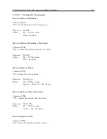
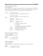
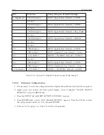
Option 28–Specific RS-232 Commands
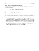
The following symbols and syntax are used throughout the RS-232 Commands listing and are
repeated here for emphasis:
C
Shorthand for Carriage–Return, Line–Feed.
“A”
Channel A.
“B”
Channel B.
“U”
UTC Time, Channel A (or B).
“L”
Local Time, Channel A (or B).
Fourteen (14) RS-232 commands are available with Option 28. The following conventions apply to
all RS-232 communications:
•
Phase angle, in all messages, is defined as zero (or 360) for the positive-going zero crossing
coincident with 1PPS-GPS, and is scaled between zero and 360 degrees. Phase angle increases
with frequency below nominal (50 or 60 Hz) and decreases with frequency above nominal;
in other words, if the zero crossing occurs just after 1PPS-GPS, the phase angle will be just
above zero, and if the zero crossing occurs just prior to 1PPS-GPS, phase angle will be just
under 360.
•
Time deviation decreases (becomes more negative) with frequency below nominal, and in-
creases (becomes more positive) with frequency above nominal.
Summary of Contents for 1088A
Page 4: ...iv ...
Page 6: ...vi ...
Page 18: ...xviii LIST OF FIGURES ...
Page 23: ...1 4 Attaching Rack Mount Ears to 1088A B Series Clocks 3 Figure 1 2 Attaching Rack Mount Ears ...
Page 24: ...4 Unpacking the Clock ...
Page 32: ...12 Front and Rear Panels ...
Page 38: ...18 Connecting Inlet Power Input and Output Signals ...
Page 46: ...26 GPS Antenna and Cable Information ...
Page 48: ...28 Setting Internal Jumpers Figure 5 1 Model 1088B Main Board ...
Page 76: ...56 The Setup Menus ...
Page 112: ...92 Serial Communication and Command Set ...
Page 127: ...B 4 Physical Dimensions 107 Figure B 1 Suggested Mounting of the AS0094500 Surge Arrester ...
Page 128: ...108 Using Surge Arresters ...
Page 145: ...C 5 Option 04 Parallel BCD Output 125 Figure C 4 Option 04 Output Jumper Settings ...
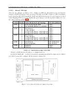
Page 146: ...126 Options List Figure C 5 Option 04 Board Layout and Jumper Locations ...
Page 166: ...146 Options List Figure C 12 Option 17 Board Layout and Jumper Locations ...
Page 187: ...C 16 Option 20A Four Fiber Optic Outputs 167 Figure C 22 Option 20A Jumper Locations ...
Page 194: ...174 Options List Figure C 24 Option 23 Internal Jumper Setup ...
Page 196: ...176 Options List Figure C 25 Option 27 Jumper Locations ...
Page 214: ...194 Options List Figure C 28 Option 29 Connector Signal Locations ...
Page 270: ...250 Options List ...


