C.22 Option 34: NTP/PTP Server
205
After the Clock and Server Have Stabilized
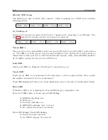
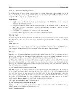
After the GPS clock and the Option 34 have stabilized, press the SYSTEM button to view server
status, link status and port addresses (IP and MAC address).
Server Status
NTP: SYNCHRONIZED
PTP: RUNNING
Link Status: indicates whether the network connection is good or bad. Status will also indicate
BAD LINK if a network cable IS NOT connected to the port.
NET1:
GOOD LINK
NET2:
BAD LINK
Port Address:
NET1:192.168.000.232
64:73:E2:XX:XX:XX
To Determine IP Address using RS-232 Commands
Type “IP” in the terminal window and the clock should return the IP and MAC addresses for both
ports in separate lines. The IP command will return dashes for an IP address when no cable is
connected to that port.
Option 34 LED Indications
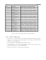
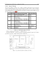
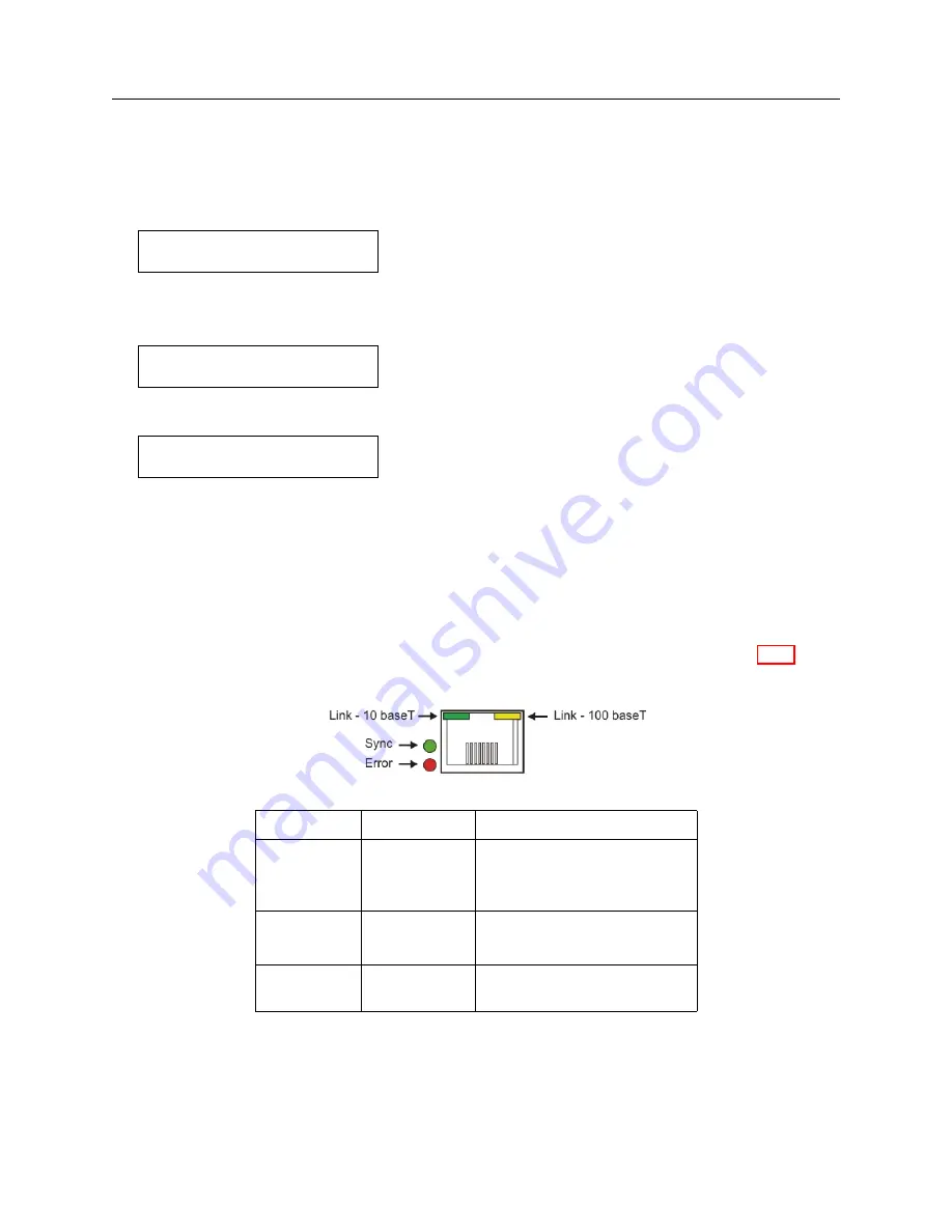
To view the Option 34 Status LEDs, see the Option 34 rear panel. The figure and Table C.16 below
describe the indications.
LED Name
Color
Meaning
LINK
Steady Green
Good Link, 10 Mb/s
Steady Yellow
Good Link, 100 Mb/s
OFF
Bad Link, e.g. no connection
SYNC
Steady Green
NTP Server Synchronized
OFF
NTP Server not Synchronized
ERROR
Red
Startup/Error
OFF
No Errors
Table C.16: Option 34 LED Indications
Summary of Contents for 1088A
Page 4: ...iv ...
Page 6: ...vi ...
Page 18: ...xviii LIST OF FIGURES ...
Page 23: ...1 4 Attaching Rack Mount Ears to 1088A B Series Clocks 3 Figure 1 2 Attaching Rack Mount Ears ...
Page 24: ...4 Unpacking the Clock ...
Page 32: ...12 Front and Rear Panels ...
Page 38: ...18 Connecting Inlet Power Input and Output Signals ...
Page 46: ...26 GPS Antenna and Cable Information ...
Page 48: ...28 Setting Internal Jumpers Figure 5 1 Model 1088B Main Board ...
Page 76: ...56 The Setup Menus ...
Page 112: ...92 Serial Communication and Command Set ...
Page 127: ...B 4 Physical Dimensions 107 Figure B 1 Suggested Mounting of the AS0094500 Surge Arrester ...
Page 128: ...108 Using Surge Arresters ...
Page 145: ...C 5 Option 04 Parallel BCD Output 125 Figure C 4 Option 04 Output Jumper Settings ...
Page 146: ...126 Options List Figure C 5 Option 04 Board Layout and Jumper Locations ...
Page 166: ...146 Options List Figure C 12 Option 17 Board Layout and Jumper Locations ...
Page 187: ...C 16 Option 20A Four Fiber Optic Outputs 167 Figure C 22 Option 20A Jumper Locations ...
Page 194: ...174 Options List Figure C 24 Option 23 Internal Jumper Setup ...
Page 196: ...176 Options List Figure C 25 Option 27 Jumper Locations ...
Page 214: ...194 Options List Figure C 28 Option 29 Connector Signal Locations ...
Page 270: ...250 Options List ...


