58
Timing, IRIG-B and Pulses
7.2
Timing Output Description
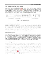
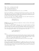
When viewing the rear panel of the Model 1088B, you will see that there are a number of different
types of connectors as illustrated in Figure 7.1. Generally, there is a power inlet connector, a GPS
antenna connector, one DB-9 serial connectors, a series of four connector plugs and one option
plate. The hole plugs cover the connector holes for option Slot A, and the option plate covers Slot
B, used to house accessory boards that provide additional functionality to the 1088B.
Figure 7.1: Rear Panel Descriptions
7.2.1
Standard Inputs/Outputs
The Model 1088B has four BNC female connectors that can supply up to twenty-two different
timing signals to external equipment. Two of these connectors (J3 and J4) may also be configured
for an event/deviation inputs. All of the outputs are designed for digital and analog signals that
are configured using internal jumpers. Signals supplied to the digital drivers include unmodulated
IRIG-B, many different pulse outputs per second, and programmable pulse.
7.2.2
Digital Drivers
Each digital output is driven by one of the four outputs from a single CMOS 74HC126 quad driver
capable of supplying 18 mA (each) at 5 Vdc. To determine the maximum number of devices that
each digital driver can support, you will need to determine the load current, or input impedance,
for each connected device. For example, if the IED timing input signal (e.g. IRIG-B003) requires
1 mA, one output channel should be able to support 18 such devices. If the load current is more
or less, then you can connect any number of devices up to the current limit for one output.
7.2.3
Analog Drivers
The 1088B has one analog driver per output available for modulated IRIG-B signals and
±
5 V
deviation for a chart recorder. Additional analog drivers may be added as options (e.g. Option
03, 27, 29). The analog driver uses a series of LF353 op amps, which supply a 10 Vpp signal
through a 557-ohm source resistor, or 4.5 Vpp on Option 27, to IED’s. With increasing load
current from external IED’s more voltage is dropped across the clock source resistor and the drive
voltage decreases. Matching the modulated IRIG-B output voltage to the IED input is sometimes
critical, so it is important to match the modulated IRIG-B peak-to-peak voltage to within the
specified range of the IED. Table 7.1 shows how the actual drive voltage varies with increasing load
current. For IED’s with a restricted input range, it may be necessary to match the available drive
voltage to the IED through a small dropping resistor.
Summary of Contents for 1088A
Page 4: ...iv ...
Page 6: ...vi ...
Page 18: ...xviii LIST OF FIGURES ...
Page 23: ...1 4 Attaching Rack Mount Ears to 1088A B Series Clocks 3 Figure 1 2 Attaching Rack Mount Ears ...
Page 24: ...4 Unpacking the Clock ...
Page 32: ...12 Front and Rear Panels ...
Page 38: ...18 Connecting Inlet Power Input and Output Signals ...
Page 46: ...26 GPS Antenna and Cable Information ...
Page 48: ...28 Setting Internal Jumpers Figure 5 1 Model 1088B Main Board ...
Page 76: ...56 The Setup Menus ...
Page 112: ...92 Serial Communication and Command Set ...
Page 127: ...B 4 Physical Dimensions 107 Figure B 1 Suggested Mounting of the AS0094500 Surge Arrester ...
Page 128: ...108 Using Surge Arresters ...
Page 145: ...C 5 Option 04 Parallel BCD Output 125 Figure C 4 Option 04 Output Jumper Settings ...
Page 146: ...126 Options List Figure C 5 Option 04 Board Layout and Jumper Locations ...
Page 166: ...146 Options List Figure C 12 Option 17 Board Layout and Jumper Locations ...
Page 187: ...C 16 Option 20A Four Fiber Optic Outputs 167 Figure C 22 Option 20A Jumper Locations ...
Page 194: ...174 Options List Figure C 24 Option 23 Internal Jumper Setup ...
Page 196: ...176 Options List Figure C 25 Option 27 Jumper Locations ...
Page 214: ...194 Options List Figure C 28 Option 29 Connector Signal Locations ...
Page 270: ...250 Options List ...

