72
Serial Communication and Command Set
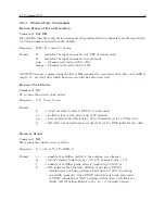
Broadcast Mode – STATUS
Command:
B4, O4
B4 configures the clock to broadcast any status data from the main RS-232C port when it changes.
O4 configures the clock to broadcast any status data from the option RS-232C port when it changes.
NOTE: When a valid fault is detected, the specific status fault is broadcast once (with Julian day,
and time) to the chosen serial port. When the fault clears, another message is sent describing the
cleared fault.
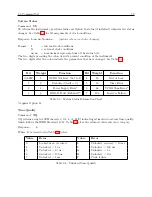
Response: ddd:hh:mm:ss I=nn:nn X=nn:nn
C
(Updates whenever the status changes.)
Where:
I, Internal clock conditions
X, External clock conditions
nn:nn, Status byte(Hex).
The 2 digits preceding the colon describe the present condition of the instrument. The 2 digits
after the colon indicate the parameters, which have changed.
Bit
Weight
Fault
Bit
Weight
Fault
0
1
OCXO Not Installed
4
16
Out-of-Lock
1
2
Stabilized (fault = 0)
5
32
Time Error
2
4
Power Supply Error*
6
64
VCXO Error**
3
8
IRIG Fault (External)*
7
128
Receiver Failure
Table 9.1: Fault Indications and Definitions
*requires Option 18, **out of bounds
Summary of Contents for 1088A
Page 4: ...iv ...
Page 6: ...vi ...
Page 18: ...xviii LIST OF FIGURES ...
Page 23: ...1 4 Attaching Rack Mount Ears to 1088A B Series Clocks 3 Figure 1 2 Attaching Rack Mount Ears ...
Page 24: ...4 Unpacking the Clock ...
Page 32: ...12 Front and Rear Panels ...
Page 38: ...18 Connecting Inlet Power Input and Output Signals ...
Page 46: ...26 GPS Antenna and Cable Information ...
Page 48: ...28 Setting Internal Jumpers Figure 5 1 Model 1088B Main Board ...
Page 76: ...56 The Setup Menus ...
Page 112: ...92 Serial Communication and Command Set ...
Page 127: ...B 4 Physical Dimensions 107 Figure B 1 Suggested Mounting of the AS0094500 Surge Arrester ...
Page 128: ...108 Using Surge Arresters ...
Page 145: ...C 5 Option 04 Parallel BCD Output 125 Figure C 4 Option 04 Output Jumper Settings ...
Page 146: ...126 Options List Figure C 5 Option 04 Board Layout and Jumper Locations ...
Page 166: ...146 Options List Figure C 12 Option 17 Board Layout and Jumper Locations ...
Page 187: ...C 16 Option 20A Four Fiber Optic Outputs 167 Figure C 22 Option 20A Jumper Locations ...
Page 194: ...174 Options List Figure C 24 Option 23 Internal Jumper Setup ...
Page 196: ...176 Options List Figure C 25 Option 27 Jumper Locations ...
Page 214: ...194 Options List Figure C 28 Option 29 Connector Signal Locations ...
Page 270: ...250 Options List ...

