3. Mount the pipe nipple to a fixture, such as the side or top of a building, or to a pipe. You
may also purchase the antenna mounting kit (AS0044600) available from Arbiter Systems.
4. Also available is a surge arrester (AS0094500) that can protect the Model 1088 from induced
voltages that may appear on the antenna cable.
5. Connect the antenna cable to the clock so the clock can synchronize with the GPS.
Installing the Clock in a Rack
Align the ears of the two rack-mount ears with the mounting holes in a standard 19-inch rack and
secure with the rack hardware.
Connecting Signal Cables
Connecting cables to the clock is fairly straightforward. For changing signal types on any of the
ports, please see the operation manual which discusses jumper settings.
RS-232C
Antenna
Power Supply
Voltages
AC & DC
Fuse Type
S
er
ial
N
um
b
er
J5 J4 J3 J2
Optional I/O
Optional Outputs
Standard Outputs
RS232 Port
Antenna
Power Inlet
•
Timing Outputs
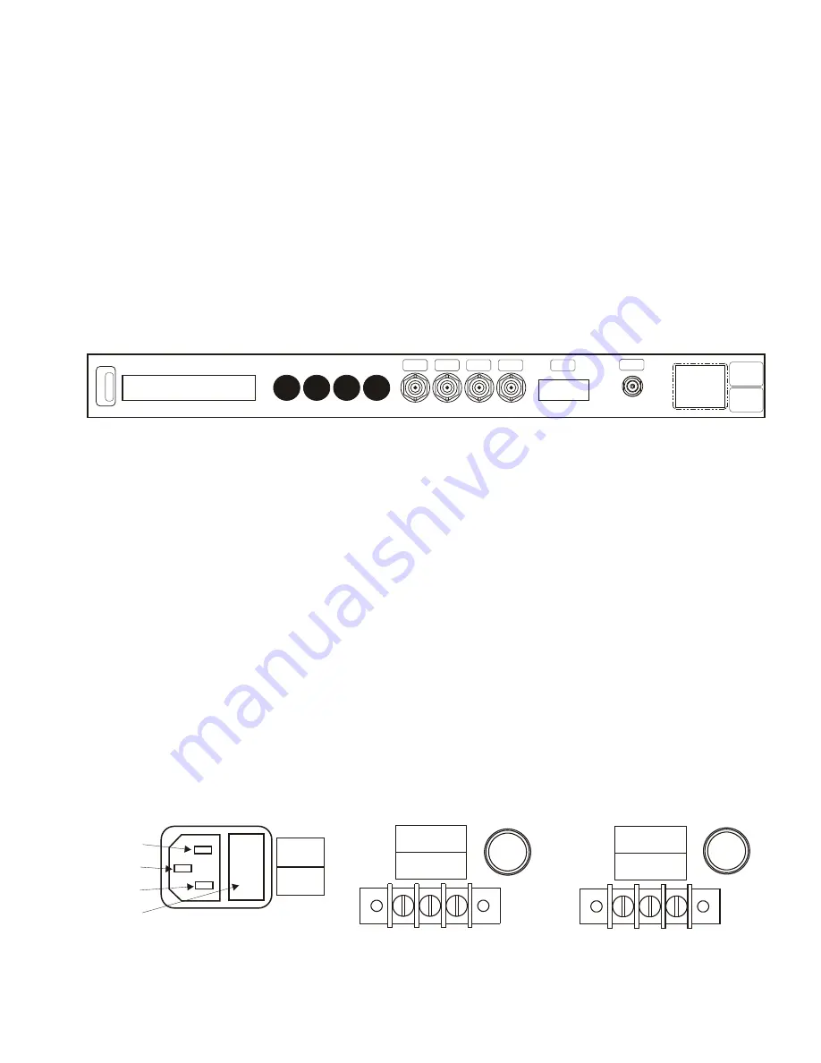
Model 1088B has four BNC female connectors at the rear panel. Besides
standard unmodulated IRIG-B, modulated IRIG-B and 1 Pulse Per Second, there are 22 total
timing signals that may be selected. Connect cables to the appropriate timing signal.
•
Fiber Optic
If your clock has one or more fiber optic connectors, remove the protective caps
and connect the fiber optic cables.
•
Out-of-Lock Relay
If equipped with Option 19 out-of-lock relay, connect the three wires
to the SPDT relay contact terminals. Strip the wire insulation about 1/4 in and DO NOT
TIN WITH SOLDER the bare wire.
•
RS232 ports
Connect a null-modem serial cable between the computer and the clock. A
USB-to-serial adapter may be required.
•
Network ports
If the clock has Option 34 installed, connect network cables to either a
copper RJ-45 connector or type LC fiber optic connector, whichever is present.
Energizing the Clock
Before connecting voltages to the clock, make sure to read the power inlet label to verify the correct
voltage. Make sure that the voltage you are connecting is in the correct range supplied on the label.
The figures shown indicate the three types of inlet supplies available. For the Standard IEC-320
Inlet, a fuse is located behind a snap-fit latch on the right side of the connector. For Options 07
and 08, a fuse is located to the right of each power inlet connector.
Standard IEC-320 Power Inlet
Option 07 Power Inlet
Option 08 Power Inlet
85 - 264 Vac
47 - 440 Hz
110 - 350 Vdc
<20W Typ.
FUSE
1AF/250V
110 – 250 Vdc
85 – 264 Vac
(47 – 440 Hz) 3 W Typ.
FUSE
1AF / 250 V
+ – GND
LINE
10 – 60 Vdc
3 W Typical
FUSE
2AT/250V
+ – GND
Neutral
Ground
Line
Fuse Compartment
2


