


118
Options List
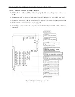
Set 50/60 Hz Input, and Return to Main Menu. Select the desired choices. When complete (if
this is the first time these options have been activated), turn the clock OFF and back ON again to
initialize the Option Boards.
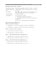
View the deviations on the front panel display as follows:
1. To view Channel C, press the EVENT/DEVIATION key and observe the following display
on the front panel (values are representative):
System Input 114.91 V
Phase 359.60
◦
2. Press the EVENT/DEVIATION key again and the following is displayed:
System
∆
F -0.0010 Hz
∆
T +0.0000 Sec
3. Press the EVENT/DEVIATION key again and the following is displayed:
System Frq 59.993 Hz
Time 19:39:25.4327
NOTE:
Selection of Option 28 results in the deactivation of the Event front panel displays.
The event displays may be re-enabled if desired, by entering the SET EVENT/DEVIATION
menu and following the procedure below. This choice is only available when Option 28 is
installed in the unit.
4. Use the SETUP key and access the SET EVENT DEVIATION ? setup menu. Press ENTER.
The following is displayed:
DISPLAY OPT 28 ONLY?
UP = YES DOWN = NO
5. To view Option 28 only, press the UP key, then press the front panel key EVENT /DEVIA-
TION to display Option 28 measurement information.
6. To enable Event/Deviation A and B displays as well, press the DOWN key and config-
ure the Channel Mode, Time, and Recorder Channel.
Then press the front-panel key
EVENT/DEVIATION to sequentially display all three channels. For a detailed description,
refer to Section 5.3.4.
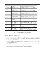
C.12.5
Calibration
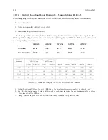
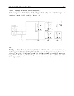
The clock is now configured for operation. Calibration for phase and amplitude may be further per-
formed. Specifically, these calibrations have no effect on system time and frequency measurements,
and are unnecessary if only time and frequency are required.
Uncalibrated phase accuracy is usually less than 0
.
3
◦
, and can be reduced to 0
.
1
◦
typical and
0.2 degree guaranteed with calibration. Uncalibrated amplitude accuracy is usually less than 1%,
which is the typical performance of this measurement. Amplitude accuracy is not guaranteed, and
amplitude measurements are provided primarily to verify that the unit is properly connected and
receiving the expected signal level.
Summary of Contents for 1092A
Page 4: ...iv ...
Page 18: ...xviii LIST OF TABLES ...
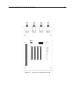
Page 129: ...C 10 Option 20A Four Fiber Optic Outputs 111 Figure C 7 Option 20A Jumper Locations ...
Page 131: ...C 11 Option 27 8 Channel High Drive 113 Figure C 8 Option 27 Jumper Locations ...
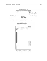
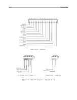
Page 148: ...130 Options List Figure C 10 Option 29 Connector Signal Locations ...


