


C.12 Option 28: Power System Time, Frequency and Phase Monitor
117
C.12
Option 28: Power System Time, Frequency and Phase Mon-
itor
C.12.1
General Description
This document describes Option 28 Power System Time, Frequency, and Phase Monitor, which is
used in the Arbiter Systems line of standard Satellite-Controlled Clocks.
C.12.2
Discussion
Option 28 provides the clock with the ability to accept either a 50 Hz or 60 Hz, 30-300 Vrms
signal input and measure the instantaneous phase, magnitude and frequency of the fundamental
component while rejecting the effects of harmonics, noise and DC offsets. This option also integrates
total time deviation, which is system time minus GPS time. Measurement results may be output
via the rear-panel RS-232 connector or displayed on the front panel. To determine phase shift
across a transmission line, the measured phase angles from two units placed at the ends of the line
are subtracted and normalized into the range of 0-360 (or
±
180) degrees. By subtracting the two
measurements of absolute phase, which are measured using the same (GPS time) reference, the
reference cancels leaving the phase angle between the two units: A-B = (A-R) - (B-R).
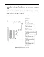
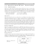
C.12.3
System Reference Connection
To connect the Option 28 board to the system reference input perform the following steps:
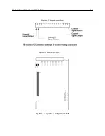
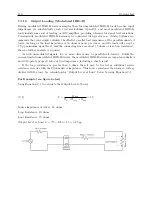
1. Connect System Reference (50 or 60 Hz signal) input to the Option 28 assembly, using the 6
m (20 ft.) length of twin axial cable provided. Strip the unterminated end of this cable and
prepare it as required for termination to your System Reference signal. Do not connect the
shield of the cable at the reference input end.
2. Attach this cable to the Option 28 System Reference input. Hold the cable connector by its
body (not by the rotating locking ring) and rotate it inside the twin-BNC connector until
you feel it begin to mate with the twin-BNC input of the Option 28 assembly. Once the
connectors begin to mate, then use the locking ring to secure the connectors together.
CAUTION:
The twin-BNC connector, unlike a standard BNC connector, will only mate prop-
erly in one orientation, and any attempt to force the connector into position with the locking ring
when it is improperly oriented (as may be done with standard BNC connectors) will not work and
may damage the connector.
NOTE:
The supplied cable is terminated at one end with a twin-BNC connector which mates
with the system reference input of the Option 28 board.
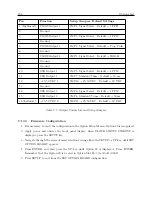
C.12.4
Firmware Configuration
Apply power and observe front panel display, when CLOCK STATUS STARTUP is displayed, press
the SETUP key.
Navigate through the series of menu selections, using either the DOWN, UP or SETUP key,
until SET OPTION BOARD? appears. Press ENTER and navigate to AUX. BOARD OPTION.
Press ENTER, and then press the UP key until Option 28 is displayed. Press ENTER. You
will be given additional setup choices for Option 28; Set System Time Dev?, Set UTC/Local Time,
Summary of Contents for 1092A
Page 4: ...iv ...
Page 18: ...xviii LIST OF TABLES ...
Page 129: ...C 10 Option 20A Four Fiber Optic Outputs 111 Figure C 7 Option 20A Jumper Locations ...
Page 131: ...C 11 Option 27 8 Channel High Drive 113 Figure C 8 Option 27 Jumper Locations ...
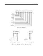
Page 148: ...130 Options List Figure C 10 Option 29 Connector Signal Locations ...


