


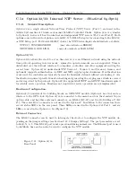


C.14 Option 32/33: Internal NTP Server –
Obsoleted by Opt34
131
C.14
Option 32/33: Internal NTP Server –
Obsoleted by Opt34
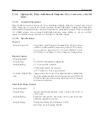
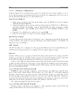
C.14.1
General Description
Option 32 is a single internal Network Time Protocol (NTP) Server (Port 1), and used in the
Arbiter Systems line of 19-inch, rack mount Satellite-Controlled Clocks. Option 33 is very similar
to Option 32, however it has two identical and independent NTP servers (Port 1 and Port 2). Both
options come with a six-foot phone cord and RJ-11 to DB-9F adapter for connecting to the RS-232,
or NTP Setup, port. For Model 1093B/C clocks, the NTP Status display should indicate as follows:
NTP1(2): SYNCHRONIZED
(may also indicate as ERROR)
NETWORK: GOOD LINK
(may also indicate as BAD LINK)
Option 32/33
Option 32/33 allows the clock to act as time server over an Ethernet network using the network
time protocol operating in server mode - symmetric operation modes are not supported. Time is
distributed over the network interface to computers, controllers and other equipment needing the
correct time. Option 32/33 understands NTP Version 1, Version 2, and Version 3 frames, and
optionally supports authentication via DES and MD5 cryptographic checksums. If authentication
is not used, the controller can typically be used for hundreds of clients without overloading it. Au-
thentication requires typically 40 ms for checking and generating the cryptograms, which is covered
and averaged out by the protocol. Option 32/33 supports full SNTP and all NTP functions required
for reliable server operation. Functions not required for server operation are not implemented.
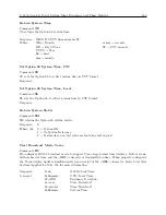
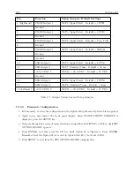
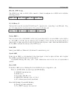
Hardware Configuration.
Option 32/33 consists of two building blocks; an OEM NTP module (Option 33 has two) and an
interface to the GPS clock. Option 32/33 is connected to the main board via the standard 50 pin
option cable, and has three external connectors, an RS-232 (RJ-11) and two 10/100 Base-T (RJ
45). The center RJ-45 connector is not used in the Option 32. In addition to the connectors there
are six status LED’s on the rear panel. Three LEDs are used in the Option 32 at Port 1, and six
LEDs are used in the Option 33. See Figure C.11.
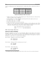
External Connectors
The RS-232 connector can be used to interrogate the clock or to configure the NTP module de-
pending on the jumper settings (see Section C.14.2 Jumper Settings). The port parameters are set
to 9600, N, 8, 1. This RS-232 port is not operational during normal use. The Ethernet port is used
to distribute time and can also be used to configure the NTP module.
Figure C.11: Option 32/33
Rear Panel
Summary of Contents for 1092A
Page 4: ...iv ...
Page 18: ...xviii LIST OF TABLES ...
Page 129: ...C 10 Option 20A Four Fiber Optic Outputs 111 Figure C 7 Option 20A Jumper Locations ...
Page 131: ...C 11 Option 27 8 Channel High Drive 113 Figure C 8 Option 27 Jumper Locations ...
Page 148: ...130 Options List Figure C 10 Option 29 Connector Signal Locations ...


