


132
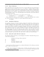
Options List
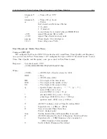
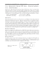
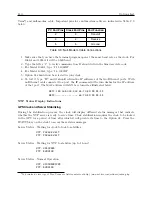
RS-232, NTP Setup
The RS-232 port uses an RJ-11 style connector, which is configured as a DTE device with the
following pin out:
GND = Pin 2
TXD = Pin 3
RXD = Pin 4
GND = Pin 5
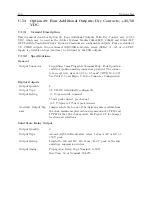
10/100 Base-T
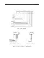
Option 32/33 uses the standard 10/100 base-T connection for connecting to an Ethernet. Fig-
ure C.11 indicates the location of pin 1 (two places for Option 33).
TXD+ = Pin 1
TXD– = Pin 2
RXD+ = Pin 3
RXD– = Pin 6
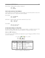
Status LED’s
There are three active status LED’s on the rear panel of Option 32; six active LED’s on the Option
33. The LED’s are Link (green), Synch (green) and Error (red). Option 32/33 will perform an
initial self test when powered on. After the initial self-test phase, where all status LEDs should be
lit, the LED’s indicate the status of the NTP Server.
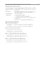
Link LED
Link (green) LED on: Ethernet 10/100 base-T connection is good.
Synch LED
Synch (green) LED on: synchronized to the time signal, correct reception of time data, requires
the satellite controlled clock to be synchronized.
Synch LED flashing 50% duty cycle: Some information received, but not yet synchronized
reliably.
Error LED
If the Error LED is on or blinking the Synch LED will give a diagnostics code.
Error (red) LED stable on, Synch (green) LED flashing
1x: EPROM-checksum error
2x: RAM-error
3x: Network controller error
4x: EEPROM checksum error, or is bad
5x: IP address already used on network
Error LED flashing, Synch LED flashing
4x: Faulty network connection
5x: No DHCP response was received
Summary of Contents for 1092A
Page 4: ...iv ...
Page 18: ...xviii LIST OF TABLES ...
Page 129: ...C 10 Option 20A Four Fiber Optic Outputs 111 Figure C 7 Option 20A Jumper Locations ...
Page 131: ...C 11 Option 27 8 Channel High Drive 113 Figure C 8 Option 27 Jumper Locations ...
Page 148: ...130 Options List Figure C 10 Option 29 Connector Signal Locations ...


