


C.14 Option 32/33: Internal NTP Server –
Obsoleted by Opt34
133
C.14.2
Jumper Settings.
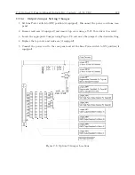
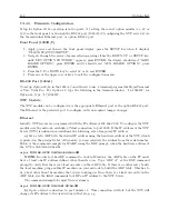
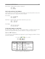
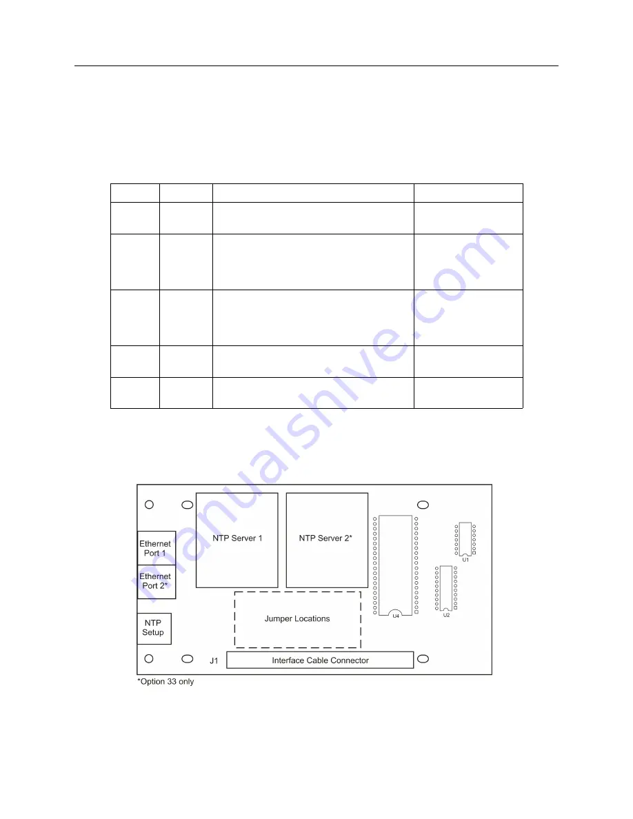
There are five jumpers on Option 32/33. Jumper 1 (JMP1) is determined by the clock model;
Jumper 2 (JMP2) determines board operation with JMP3 and JMP4; Jumper 3 (JMP3) determines
board operation with JMP2 and JMP4; JMP2 and JMP3 always move as a pair; Jumper 4 is used
with configuring NTP servers over the RS-232 port; Jumper 5 sets the board for Option 32 or 33.
See jumper settings in Table C.8.
Jumper
Position
Option Mode (Rev.B and following)
Rev.A Board Modes
JMP1
A
Determined by Model 1088B
(same)
B
Det. by Model 1084A/B/C or 1093A/B/C
(same)
JMP2
A
NTP Server(s)
(same)
B
Clock serial port
(same)
C
Configure NTP Server 1* via RS-232 only
(same)
D
Configure NTP Server 2* via RS-232 only
(same)
JMP3
A
NTP Server(s)
(same)
B
Clock serial port
(same)
C
Configure NTP Server 1* via RS-232 only
(same)
D
Configure NTP Server 2* via RS-232 only
(same)
JMP4
A
NTP Server(s)
NTP Configuration
B
NTP Configuration
NTP Server(s)
JMP5
A
Option 33
(same)
B
Option 32
(same)
Table C.8: Option 32/33 Jumper Truth Table – *Must set JMP4 into the Configuration mode – “B”
position for Rev B or later boards, “A” position for Rev. A boards.
Figure C.12: Option 32/33 Board, Jumper Locations
Summary of Contents for 1092A
Page 4: ...iv ...
Page 18: ...xviii LIST OF TABLES ...
Page 129: ...C 10 Option 20A Four Fiber Optic Outputs 111 Figure C 7 Option 20A Jumper Locations ...
Page 131: ...C 11 Option 27 8 Channel High Drive 113 Figure C 8 Option 27 Jumper Locations ...
Page 148: ...130 Options List Figure C 10 Option 29 Connector Signal Locations ...