background image

174

Options List

DESCRIPTION “ String identifier for the NTP System Group.”
::=

{

ntpsys 1

}

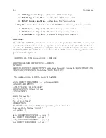
ntpSysClock OBJECT-TYPE
SYNTAX OCTET STRING
MAX-ACCESS read-only
STATUS current
DESCRIPTION “the current local time. Local time is derived
from the hardware clock of the particular machine and
increments at intervals depending on the design used.”
::=

{

ntpsys 2

}

ntpSysClockDateTime OBJECT-TYPE
SYNTAX OCTET STRING
MAX-ACCESS read-only
STATUS current
DESCRIPTION “the current local time. Local time is derived
from the hardware clock of the particular machine and
increments at intervals depending on the design used.”
::=

{

ntpsys 3

}

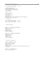
ntpSysOffset OBJECT-TYPE
SYNTAX Integer32
MAX-ACCESS read-only
STATUS current
DESCRIPTION “”
::=

{

ntpsys 4

}

ntpSysFreq OBJECT-TYPE
SYNTAX MilliUnits
MAX-ACCESS read-only
STATUS current
DESCRIPTION “”
::=

{

ntpsys 5

}

ntpSysSysJitter OBJECT-TYPE
SYNTAX MilliUnits
MAX-ACCESS read-only
STATUS current
DESCRIPTION “”
::=

{

ntpsys 6

}

ntpSysClkJitter OBJECT-TYPE
SYNTAX MilliUnits
MAX-ACCESS read-only
STATUS current

Summary of Contents for 1092A

Page 1: ...MODEL 1092A B C MODEL 1093A B C SATELLITE CONTROLLED CLOCK OPERATION MANUAL ARBITER SYSTEMS INC PASO ROBLES CA 93446 U S A WWW ARBITER COM ...

Page 2: ...l 1093A B C series satellite controlled clocks How to Determine Firmware Version Date To display the firmware date for your instrument Models 1092B 1093B and 1093C only press and release the SETUP key at power up and the date should appear briefly on the LCD display To display the firmware date for Models 1092A 1092C and 1093A use the main RS 232 port see page 10 2 15 To determine the current firm...

Page 3: ...URPOSE AND BUYER EXPRESSLY WAIVES ALL OTHER WARRANTIES This limited warranty does not extend to any product which has been subject to 1 Improper use or application abuse or operation beyond its rated capacity or contrary to the instructions in the operation and maintenance manuals if any 2 Accident 3 Repair or maintenance performed by Buyer except in accordance with the operation and maintenance m...

Page 4: ...iv ...

Page 5: ...r 6 Startup and Basic Operation Chapter 7 The Setup Menus Chapter 8 Timing IRIG B and Pulses Chapter 9 Relay Contacts and Event Inputs Chapter 10 Serial Communications and Command Set Appendix A Specifications and Technical Details Appendix B Using a Surge Arrester Appendix C Options List Appendix D CE Mark Certification Appendix E Statement of Compliance Index Copyright Arbiter Systems Incorporat...

Page 6: ...ation and Connectors 7 2 3 1 Power Inlet 7 2 3 2 Antenna Input 8 2 3 3 Event Input 8 2 3 4 RS 232 and RS 485 Communication Ports 8 2 3 5 Form C Relay Contacts Option 93 9 2 3 6 Standard Inputs Outputs 9 3 Connecting Inlet Power Input and Output Signals 10 3 1 Option 07 IEC 320 Power Inlet Module 10 3 1 1 Cordsets and Plug Styles for Option 07 10 3 1 2 Option 07 Connecting Power to the 1093B 10 3 2...

Page 7: ... Used as Event Capture Input JMP7 23 5 3 5 Output Signal Select JMP1 and JMP2 24 5 3 6 Data Backup Battery JMP5 Option 02 Obsolete 24 5 3 7 RS 232 AUX Out JMP6 24 6 Startup and Basic Operation 25 6 1 Initial Startup Sequence 25 6 1 1 Clock Time Startup Mode 1092B 1093B C 26 6 2 Front Panel Indication 1092B 1093B C 26 6 2 1 Display Indication at Startup 26 6 2 2 Other Display Indications When Unloc...

Page 8: ...Trigger 43 7 8 6 Programmable Pulse Slow Code 44 7 8 7 Programmable Pulse Pulse Polarity 44 7 9 Setting IRIG Time Data 45 7 10 Setting the Event or Deviation Modes 45 7 11 Setting the Auto Survey Mode 46 7 11 1 Number of Fixes 46 7 12 Setting Position Hold ON or OFF 47 7 13 Setting Option Control 48 8 Timing IRIG B and Pulses 49 8 1 Introduction 49 8 2 Timing Output Description 49 8 2 1 Inputs and...

Page 9: ... Firmware Setup 60 9 2 7 Displaying Data 60 9 2 8 RS 232C Event Trapping 61 9 2 9 Event Trapping Setup 61 10 Serial Communication and Command Set 62 10 1 Introduction 62 10 2 Command Set 62 10 2 1 Custom String Command 63 10 2 2 String Setup Examples and Tutorial 66 10 2 3 Broadcast Mode Commands 69 10 2 4 Event Mode Commands 74 10 2 5 Status Mode Commands 75 10 2 6 Local Daylight Saving Time Setu...

Page 10: ...232C Port 90 A 4 2 Broadcast Data Formats 90 A 5 Antenna System 90 A 5 1 Antenna Cable 90 A 6 Operator Interface 91 A 6 1 Setup Methods 91 A 6 2 Setup Functions 91 A 6 3 Display 91 A 6 4 Display Functions 91 A 6 5 Annunciators 91 A 7 Physical Specifications 92 A 7 1 Dimensions 92 A 7 2 Weight 92 A 8 Temperature and Humidity 92 A 9 Power Requirements 92 A 9 1 Power Connector Model 1093A B C 92 A 9 ...

Page 11: ...iption 107 C 8 1 110 to 350 VDC 85 to 250 VAC 47 to 440 Hz Terminal Power Strip SWC 107 C 8 2 Specifications 107 C 9 Option 19 Second RS 232C Interface 108 C 9 1 General Description 108 C 9 2 Specification 108 C 10 Option 20A Four Fiber Optic Outputs 109 C 11 Option 27 8 Channel High Drive 112 C 11 1 General Description 112 C 11 2 Specifications 112 C 11 3 Option Setup 112 C 11 4 Output Load and L...

Page 12: ...6 C 15 6 Specifications 178 C 15 7 HTTPS SSL Certificate 179 C 15 8 Time Zone Format Strings 181 C 16 Option 36 Four Configurable Outputs 182 C 16 1 General Description 182 C 16 2 Specifications 182 C 16 3 Changing Outputs via Internal Settings 182 C 17 Option 91 1 Microsecond Accuracy RAIM Obsolete 185 C 18 Option 92 IRIG B Modulated Output 185 C 19 Option 93 Out of Lock Relay 185 C 20 Option 94 ...

Page 13: ...Option 07 Power Supply Inlet Description 10 3 2 Option 08 Power Supply Inlet Description 11 3 3 Option 10 Power Supply Inlet Description 12 4 1 Antenna Assembly for Mounting 15 4 2 Antenna Mounting Bracket 16 4 3 Antenna Mounting with AS0044600 16 4 4 GPS Surge Arrester 17 5 1 Main board and Jumper Locations 22 7 1 Main RS 232 Setup 33 7 2 Port Parameter Setup 34 7 3 Broadcast Setup 34 7 4 Local H...

Page 14: ... 107 C 7 Option 20A Jumper Locations 111 C 8 Option 27 Jumper Locations 113 C 9 Option 29 Jumper Locations 129 C 10 Option 29 Connector Signal Locations 130 C 11 Option 32 33 Rear Panel 131 C 12 Option 32 33 Board Jumper Locations 133 C 13 Startup Page 143 C 14 System Configure Page 144 C 15 Configure HTTPS 144 C 16 Configure System Password 145 C 17 Update System Firmware Package 145 C 18 Rebooti...

Page 15: ...ings Using SSH 160 C 36 View Operation Using SSH 161 C 37 View SNMP Operation Using SSH 161 C 38 PTP Status Page Using SSH 162 C 39 NTP Status Page Using SSH 162 C 40 NTP Configure Page Using SSH 163 C 41 NTP Authentication Page Using SSH 164 C 42 Contact and Version Information Pages Using SSH 165 C 43 Option 36 Jumper Configuration 184 C 44 Option 95 Rear Panel Layout 186 ...

Page 16: ...inal 01 65 10 3 List of True Time Quality Levels Ordinal 02 65 10 4 Short Table of ASCII Characters 69 10 5 Fault Indications and Definitions 70 10 6 Survey Sn Position Hold Status Pm 77 10 7 Unlocked Time Quality 78 10 8 Auto Survey Setup Conditions 83 10 9 Option Control Settings 86 10 10Main RS 232 Port Pin Definitions 87 A 1 Setup Functions Listed 91 A 2 Clock and Antenna Dimensions 92 A 3 Clo...

Page 17: ...oadcast Time Deviation Values 122 C 7 Output Connectors and Setup Jumpers 128 C 8 Option 32 33 Jumper Truth Table 133 C 9 Null Modem Cable Connections 140 C 10 Option 34 LED Indications 141 C 11 Option 36 Output Connector Jumper Settings 184 ...

Page 18: ...xviii LIST OF TABLES ...

Page 19: ...lace before the final installation Static Discharge Note that the Model 1092A B C and 1093A B C are electronic devices and use static sensitive components in their operation Therefore use care when handling against static discharges Generally these components are protected in their normal situation however some of these are accessible when the cover is removed CAUTION Antenna Input Connector Conne...

Page 20: ...d in the packing foam side labeled ADDI TIONAL PARTS INSIDE 1 4 Attaching Rack Mount Ears to 1093A B C Series Clocks Each Model 1093A B C comes with two rack mount ears suitable for mounting in a 19 inch system rack These ears have four mounting holes two of which are used to attach them to the sides of the clock Since it is required to remove the M25 x 10 mm screws which attach the cover to the c...

Page 21: ...e a good time to make any changes to jumper settings See Chapter 5 Setting Internal Jumpers for information on doing this 1 4 2 Rack Mount Ears for Model 1092A B C Series Clocks Rack mount ears are available for Model 1092A B C series clocks by ordering part number AS0044500 These ears are similar to the rack mount ears for 1093A B C however the ears are wider to accommodate the narrower width of ...

Page 22: ... connectors controls and displays found on the front and rear panels of the 1092A B C and 1093A B C series clocks Take care to review all of these items prior to connecting cables to and configuring these products Figure 2 1 Model 1092A B C and 1093A B C Front Panel Description ...

Page 23: ...or the annunciator LEDs are found below and definitions for keys in Table 2 1 Each of four upper keys allows you to view specific clock information such as time and date geographical position and instrument status Each of the four lower keys allows you to configure various clock functions To configure see Chapter 7 The Setup Menus 2 2 1 Command Key Definitions Table 2 1 subdivides all of the funct...

Page 24: ... key will cause the display to scroll through all four modes continuously Changing the time display has no effect on the time data which is output from rear panel timing outputs Position Cycles the display through the longitude latitude and elevation data readouts of the antenna location according to the most recent position fix Event Deviation Selects Event and or Deviation Data recorded by the s...

Page 25: ... Port Antenna IRIG B UNMOD IRIG B MOD 1 PPS LOCK ERR OK COM RS 232C Power Inlet 9 Vdc 500 mA ANTENNA SERIAL NUMBER B01234 OPTION RS 232 a Figure 2 2 Model 1092A B C and 1093A B C Rear Panel Description Note Optional outputs may be shown 2 3 1 Power Inlet To cover all of the possible inlet power conditions the Model 1093A B C has three optional power supplies The Model 1092A B C series clocks have ...

Page 26: ...er and probe from the center pin of the connector to the threads Voltage range is 4 9 to 5 1 VDC For further information see Chapter 4 Antenna and Cable Information 2 3 3 Event Input For timing external events based on the GPS synchronized time use either of two event input connectors J4 Standard I O and J6 RS 232C See Figure 5 1 which illustrates the location of these two connectors and the jumpe...

Page 27: ...d Failsafe Essentially Failsafe mode occurs in the event of a power loss and the Form C relay contacts are faulted For additional information on Option 93 including specifications see Chapter 9 Relay Contacts and Event Inputs and the Options List in Section C 19 Figure 2 8 Relay Contact Connector LOCK ERR OK COM 2 3 6 Standard Inputs Outputs Figure 2 9 illustrates the timing output connector for t...

Page 28: ...e at the inlet connector before connecting power to the clock 3 1 Option 07 IEC 320 Power Inlet Module The Option 07 IEC 320 power inlet module comes with power cord for the required country code See Figure 3 1 below Inlet Specifications 85 to 264 VAC 47 to 440 Hz or 110 to 370 VDC 20 Watts Figure 3 1 Option 07 Power Supply Inlet Description Fuse Compartment Line Neutral Ground 85 264 Vac 47 440 H...

Page 29: ...1 4 Option 08 operates from common low voltage battery systems including 12 24 and 48 VDC Figure 3 2 Option 08 Power Supply Inlet Description G FUSE 1AT 250V 10 60 Vdc DC ONLY 20W Typ Ground Negative Positive Label Fuse 3 2 1 Option 08 Connecting Inlet Power When wiring station batteries to this power supply make sure to first connect an earth ground wire to the terminal strip connector labeled G ...

Page 30: ...rtment with a snap fit latch which also has a compartment for a spare fuse Check Table 3 2 for replacement fuse information The fuse compartment is located directly adjacent to the input connector socket and can be opened by pulling both sides directly out away from the chassis or by gently prying with a small flag blade screwdriver To replace the fuse first disconnect the line cord from the power...

Page 31: ...down to secure it in the connector 3 6 Connecting Input Signals Input signals may be connected through the designated I O terminals the RS 232 connector and through an installed option connector designated as Input For standard I O connectors see Section 2 3 6 Terminals are Phoenix type with 5 mm spacing and will accept between 0 25 and 2 5 mm wire diameter Option 95 has four BNC connectors and al...

Page 32: ...or all points of the compass Minimal installations where the antenna is mounted in a less favorable location may work however reception may be somewhat limited during certain hours of the day 4 1 1 Mounting the Antenna The standard antenna is designed for pole mounting on a 26 mm pole 1 05 in OD or 3 4 in ID pipe with either a standard 1 in 14 approximately M25 4 x 1 81 marine mount thread or a 3 ...

Page 33: ...or use with antennas shipped with Arbiter Systems GPS controlled clocks The hardware included with the bracket allows installation of the antenna on a mast or pipe up to about 2 in in diameter and a different clamp may be substituted for use with a larger diameter pipe Also the bracket can be mounted to a wall a roof or any other flat surface For complete details on this product request Installati...

Page 34: ...a and Cable Information Figure 4 2 Antenna Mounting Bracket Mounting bracklet Mounting bracket stabilizer U bolt backing plate U bolt 3 4 x 4 Sch 80 PVC pipe Antenna cable Figure 4 3 Antenna Mounting with AS0044600 ...

Page 35: ... clocks This signal should be between 4 9 and 5 1 VDC 4 2 3 Checking the Antenna Resistance Checking the internal resistance of the Arbiter GPS antenna is not as useful as verifying the antenna current mentioned above Antenna resistance measures several megohms with meter probes at one polarity and less so if you change the meter probe polarity 4 3 GPS Surge Arrester Figure 4 4 illustrates the GPS...

Page 36: ...l length of the cable determine cable delay During the initial factory calibration of the clock a value for cable delay based upon the length and type of cable supplied is entered into the clock memory Firmware uses this figure to counteract the effect that the delay has upon GPS timing accuracy The value entered for a standard 15 meter cable is 60 nanoseconds For other cable options the delay is ...

Page 37: ...ns 5 dB CA0021330 30 m 100 ft cable RG 6 119 ns 9 dB CA0021345 45 m 150 ft cable RG 6 177 ns 13 dB CA0021360 60 m 200 ft cable RG 6 236 ns 17 dB CA0021375 75 m 250 ft cable RG 6 295 ns 21 dB WC0004900 305 m 1000 ft roll RG 11 3 92 ns m 17 5 dB 100 m AS0044800 RG 11 crimp tool and 25 connectors N A N A AS0044700 21 dB in line amplifier 1 ns 21 dB Table 4 2 GPS Cable Data and Accessory Information P...

Page 38: ... or open circuit condition in the antenna cable will render the clock inoperable Prior to initial operation or if problems are suspected perform the Antenna Cable Operational Test Procedure described in Section 4 2 Connection to Antenna The male Type F connector on one end of the antenna cable mates with the female Type F connector on the antenna Avoid placing mechanical stress on the cable attach...

Page 39: ...On all Models disconnect the power cord If equipped with Option 04 power switch first turn the power switch to OFF 2 Using a T 25 driver remove the four screws securing the cover and rack mount ears if used Lift the cover off 5 3 Main Board Version Figure 5 1 indicates important jumper and test point locations on the main board in the Model 1092A B C and 1093A B C Use this drawing to assist you wi...

Page 40: ...g either of these jumpers the drill out via under the jumper location must be broken using a small drill in a pin vise or a sharp blade such as an X Acto knife This disconnects the original signal from the buffer input Note Vias are marked by small targets at the Jumper shown on Figure 5 1 1 Note do not attempt to change these settings on boards whose serial number begins with the digits 9636 with...

Page 41: ...e as shown on the PC board 5 3 4 I O Connector Used as Event Capture Input JMP7 With modification the Model 1092A B C and 1093A B C can accept an Event Capture input through connectors J4 or J6 I O and RS 232 respectively See Figure 5 1 To select the RS 232 input from J6 set jumper JMP7 to the A position2 To select the I O connector as the Event Input from J4 set jumper JMP7 to the B position The ...

Page 42: ...pull up will have the same polarity in either mode of operation Also note that the open drain outputs do not have any protection against reverse polarity transient over voltage or over current It is the responsibility of the user of this function to provide the necessary protection Maximum recommended operating voltage is 150 VDC 200 V peak and continuous operating current is 100 mA power limited ...

Page 43: ...low for 1092B and 1093B C clocks only The Out of Lock Relay Fault will be in the out of lock or faulted position if equipped with Option 93 Eventually the UNLOCKED LED should extinguish The Out of Lock Relay Fault should change to Locked non faulted position after a few minutes The LCD should indicate that the clock is Locked for 1092B and 1093B C clocks 1 Startup behavior is based on Models 1092B...

Page 44: ...sen for illustrative purposes only During a short period of time from a few minutes to a few seconds the displayed clock time may jump and add or lose some seconds as more satellites are acquired This is normal until the full set of ephemeris data is received by the GPS receiver from the GPS satellites when the time will be accurate At this time the Out of Lock LED will extinguish and the Out of L...

Page 45: ...ons There are three indications when successively pressing the STATUS key These are as follows CLOCK STATUS STARTUP The second line will change between STARTUP to UNLOCKED with time to NOT STABILIZED to LOCKED AUTO SURVEY to LOCKED POSITION HOLD Press status key GPS RECEIVER STATUS TRACKING 00 The number of tracked satellites can change from 0 1 12 Press status key DCXO STATUS DEVIATION nn nn PPM ...

Page 46: ...n 7 5 6 3 Clock Status Display Mode When first applying power to the clock the display will indicate several startup messages then will revert to Clock Status mode condition called STARTUP After a short time while the GPS receiver begins collecting data from the GPS it will indicate either UNLOCKED XX Min NOT STABILIZED LOCKED AUTO SURVEY or LOCKED POSITION HOLD Various faults if they exist may be...

Page 47: ...ffers from the previous format as follows UTC DATE TIME www yyyy ddd hh mm ss This mode displays UTC Time of Year mode without the application of daylight saving cor rection and local offset NOTE Daylight saving and local offset have no effect on this display 6 4 3 Date and Time Display Local Time This mode displays the date and time after the daylight saving correction and local offset have been ...

Page 48: ... the most recent position fix Press the front panel button named POSITION to access longitude latitude and elevation data values Repeatedly pressing the POSITION key scrolls the readout display continuously through these values If pressed prior to acquisition of enough satellites to accurately determine and update position data these numbers will reflect the receiver s power on defaults or display...

Page 49: ...32 commands for configuring these functions Table 7 1 lists the various menus used to configure the operation of these clock models Press the setup key to enter the clock configuration menus starting with the main RS 232 port parameters SETUP DOWN UP ENTER SETUP Press the setup key repeatedly to scroll through the main menus Also after pressing SETUP once you can press the UP or DOWN keys to scrol...

Page 50: ...ings When shipped from the factory and unless specified otherwise all models will be configured with default settings Most users elect to modify the clock settings to fit their locale and desired opera tion Default settings are listed in Table 7 2 Menu Item Default Menu Item Default Main RS 232 9600 8 N 1 Local Offset DST none OFF Out of Lock 01 minute Backlight Auto System Delays 60 ns Prog Pulse...

Page 51: ...he menu you want to change 7 3 Setting the Main RS 232 Port Press SETUP key to configure the main RS 232 port and press the ENTER key to begin setting up the RS 232 port parameters See Figure 7 1 To set up the broadcast mode press SETUP and skip to Section 7 3 2 below NOTE port settings may not be changed in the 1092A C and 1093A series clocks since they do not have a keypad and there are no port ...

Page 52: ...ENTER ODD EVEN OFF Default setting DOWN UP DOWN UP DOWN UP DOWN UP Figure 7 2 Port Parameter Setup 7 3 2 Setting the Broadcast Mode from Main RS 232 The Set Broadcast Mode menu allows you to configure any of these clock models to broadcast ASCII time date related data from the available RS 232 ports With the UP DOWN keys select the desired broadcast mode and press ENTER to immediately start the br...

Page 53: ... increments up to plus or minus 12 hours Daylight Saving is adjusted for start and stop times based on month week of month day and time of day Use this menu to set up basic DST adjustment For RS 232 command see Section 10 2 6 SET LOCAL HOUR DOWN UP ENTER SETUP SET LOCAL OFFSET HOUR MIN 00 00 ENTER SET DST SUMMER TIME OFF ENTER 12 00 00 00 12 00 AUTO ON OFF DOWN UP default setting Figure 7 4 Local ...

Page 54: ...eys to adjust the desired value and ENTER key to install that value and proceed to the next setting For RS 232 command see Section 10 2 6 SET DST SUMMER TIME AUTO ENTER SETUP DST SUMMER START DAY SUN DST SUMMER START MINUTE 0120 SAT WED SUN 0720 0120 0720 DOWN UP AUTO ON OFF DST SUMMER START MONTH MAR DEC MAR JAN DOWN UP DST SUMMER START Second SUN of MAR 3rd from Last 2nd from Last Last Third Sec...

Page 55: ... LED being ON and the optional out of lock relay Option 93 switching to the unlocked or faulted condition For RS 232 command see Section 10 2 14 Extend Relay Start increases the time for the clock to change from an unlocked to a locked indication thereby increasing clock stability at startup Normally at startup the clock waits until the GPS receiver is tracking at least four satellites before it w...

Page 56: ... 7 SET BACK LIGHT ENTER SETUP SET BACK LIGHT BACK LIGHT OFF BACK LIGHT AUTO BACK LIGHT ON BACK LIGHT OFF Default DOWN UP ENTER Figure 7 7 Back Light Setup 7 7 Setting System Delays Use the Set System Delays menu to set the delay of the GPS signal received at the GPS antenna until it reaches the GPS receiver The delay in nanoseconds 10 9 seconds is a product of the length of the cable and the its v...

Page 57: ...ccur at either UTC or Local time where applicable For RS 232 command see Section 10 2 12 SET PROG PULSE ENTER SETUP PROG PULSE MODE SEC PER PULSE DOWN UP POLARITY POLARITY SLOW CODE LCL SLOW CODE UTC SINGLE TRIGGER PULSE PER DAY PULSE PER HOUR SEC PER PULSE Default ENTER Figure 7 9 Programmable Pulse Setup 7 8 1 Entering Numerical Values When installing numerical values first use the UP DOWN keys ...

Page 58: ...il on the Programmable Pulse mode For RS 232 command see Section 10 2 12 SET PROG PULSE ENTER SETUP PROG PULSE MODE SEC PER PULSE DOWN UP SET PULSE WIDTH PULSE WIDTH 000 01 600 00 000 01 SET SEC PER PULSE 00001 SEC 60000 00001 SELECT UTC OR LOCAL PULSE TIME UTC LCL UTC Default Setting POLARITY POLARITY SLOW CODE LCL SLOW CODE UTC SINGLE TRIGGER PULSE PER DAY PULSE PER HOUR SEC PER PULSE DOWN UP DO...

Page 59: ...able pulse modes and entering numerical values For RS 232 command see Section 10 2 12 SET PROG PULSE ENTER SETUP PROG PULSE MODE PULSE PER HOUR DOWN UP SET PULSE WIDTH PULSE WIDTH 000 01 600 00 000 01 SET SEC AFTER HOUR 3599 SEC 3599 0000 SELECT UTC OR LOCAL PULSE TIME UTC LCL UTC Default Setting POLARITY POLARITY SLOW CODE LCL SLOW CODE UTC SINGLE TRIGGER PULSE PER DAY PULSE PER HOUR SEC PER PULS...

Page 60: ... 10 2 12 SET PROG PULSE ENTER SETUP PROG PULSE MODE PULSE PER DAY DOWN UP SET PULSE WIDTH PULSE WIDTH 000 01 600 00 000 01 SET PULSE TIME HOUR 00 23 00 SELECT UTC OR LOCAL PULSE TIME UTC LCL UTC Default Setting SET PULSE TIME MIN 00 59 00 SET PULSE TIME SEC 00 59 00 SET PULSE TIME SEC 00 99 00 POLARITY POLARITY SLOW CODE LCL SLOW CODE UTC SINGLE TRIGGER PULSE PER DAY PULSE PER HOUR SEC PER PULSE D...

Page 61: ...nd see Section 10 2 12 SET PROG PULSE ENTER SETUP PROG PULSE MODE SINGLE TRIGGER DOWN UP SET PULSE WIDTH PULSE WIDTH 000 01 600 00 000 01 SET TRIGGER TIME HOUR 00 DOWN UP 23 00 SELECT UTC OR LOCAL PULSE TIME UTC LCL UTC Default Setting SET TRIGGER TIME MIN 00 59 00 SET TRIGGER TIME SEC 00 59 00 SET TRIGGER TIME SEC 00 99 00 SET TRIGGER TIME DAY 001 DOWN UP 366 001 POLARITY POLARITY SLOW CODE LCL S...

Page 62: ...Polarity Use Pulse Polarity to change the pulse s OFF to ON behavior as follows 1 Positive the voltage is held low 0 VDC when the pulse is off and transitions high 5 VDC when on 2 Negative the voltage is held high 5 VDC when the pulse is off and transitions low 0 VDC when on To set up the pulse polarity first set up the programmable pulse mode e g Single Trigger and then go back into the Prog Puls...

Page 63: ...efault DOWN UP ENTER Figure 7 16 IRIG B Time Data Setup 7 10 Setting the Event or Deviation Modes Use the Event Deviation mode to capture an event input signal at any of the configured ports see Sections 5 3 4 Configure for either event timing up to 400 stored events or one pulse per second 1 PPS deviation including sigma see Section 9 2 3 for details on the principle of deviation measurement For ...

Page 64: ...rvey in progress 5 Resume Survey resume a survey that was paused SET AUTO SURVEY ENTER SETUP SELECT SURVEY MODE POWER ON SURVEY RESUME SURVEY SUSPEND SURVEY POWER ON SURVEY SINGLE SURVEY TURN OFF SURVEY DOWN UP SET OF FIXES 60 1 Mn or more 86400 300 60 1 Default setting DOWN UP ENTER ENTER Figure 7 18 Survey Mode Setup 7 11 1 Number of Fixes Auto Survey configuration presents a list of possible su...

Page 65: ...re precise timing solutions With Position Hold turned OFF the GPS receiver is placed in the Fix mode calculating a new position approximately every second as long as the GPS receiver is tracking four or more satellites For RS 232 command see Section 10 2 9 SET POSITION HOLD ENTER SETUP POSITION HOLD ON ON OFF DOWN UP ENTER Default setting Figure 7 19 Position Hold Mode Setup ...

Page 66: ...nal settings For information on configuring specific options see the Option List located in Appendix C For RS 232 command see Section 10 2 15 SET OPTION CONTROL ENTER SETUP MAIN BOARD OPTION NONE 19 NONE DOWN UP AUX BOARD OPTION NONE 35 34 33 32 29 28 27 20A 03 NONE Default setting Go to Options List in Appendix C for individual option setup instructions DOWN UP ENTER ENTER Figure 7 20 Option Cont...

Page 67: ...e the timing signal Various methods are used to configure equipment to receive IRIG B time codes including setting a physical jumper or using a setup application Some equipment can auto detect the timing signal so that nothing else is required other than connecting the cable 8 2 Timing Output Description When viewing the rear panels of the Model 1092A B C and 1093A B C you will see a number of dif...

Page 68: ...uad driver capable of supplying 75 mA at 5 VDC which may be fanned out to a number of devices To determine the number of devices you can supply calculate the load current required by each connected device For example if the IED timing signal input e g IRIG B003 requires 10 mA one digital output should be able to support eight identical devices 8 2 3 Analog Driver Modulated IRIG B is available1 at ...

Page 69: ...IRIG Standard 200 04 two of the designations have changed the older B000 has become B004 and B120 has become B124 Designation New Old Signal Type Code Components B004 B000 Pulse width code No carrier BCDT OY BCDY EAR CF SBS B003 Pulse width code No carrier BCDT OY SBS B124 B120 Sine wave amplitude modulated 1 kHz BCDT OY BCDY EAR CF SBS B123 Sine wave amplitude modulated 1 kHz BCDT OY SBS Table 8 ...

Page 70: ...thin this portion of the time code bits are designated for additional features including Calendar Year old method now called BCDY EAR Leap seconds and leap seconds pending Daylight Saving Time DST and DST pending Local time offset Time quality Parity Position identifiers To be able to use these extra bits of information protective relays RTU s and other equipment receiving the time code must be ab...

Page 71: ...minute second fractional seconds Slow code 2 seconds on the minute 4 seconds on the hour 6 sec onds on the day Pulse polarity Positive or negative going pulse Table 8 3 Programmable Pulse Modes and Features 8 3 6 Programmable Pulse with 200 Volt FET Setup For high level switching on the main board choose option 1093optS001 or 1092optS001 Clocks can provide high level switching at either of the two...

Page 72: ...involved one outgoing and one return For coaxial cable the resistance is different for the center conductor than for the outer conductor or shield For twisted pair wires both outgoing and return wires will be the same As a simple example to connect an IRIG B signal to a device 100 feet away from the clock you must account for resistive losses in 200 feet of wire For details on distributing IRIG B ...

Page 73: ... current drawn would be 10 x 0 001 A 0 01 A 10 mA Another method is to determine the lumped impedance of all of the connected IED s in parallel Then determine the overall current by dividing the drive voltage 5 V by the computed lumped impedance value This current should not exceed 75 mA 8 4 5 Connecting Modulated IRIG B While the modulated driver supplies approximately 4 5 volts peak to peak Vpp ...

Page 74: ...hort as possible use a larger diameter wire and carefully distribute the loads 8 4 7 Voltage Matching for Modulated IRIG B With modulated IRIG B it was mentioned that certain decoders are very intolerant of drive voltage variation If the IED specification says that the acceptable voltage range is 3 3 Vpp 0 5 volt and the available voltage is high then you must reduce the voltage using a dropping r...

Page 75: ...e timing signal by one microsecond For IRIG B timing applications these delays may not be important compared to other criteria Otherwise you would be forced to compensate for the time delay using another method such as advancing the timing output or placing another master clock at the remote site 8 4 9 Solutions There are many solutions to providing an accurate timing signal to equipment in distan...

Page 76: ...PS The faulted indication is as follows ERR Normally Closed is shorted to COM and OK Normally Open is open with respect to COM If the clock loses synchronization with the GPS the out of lock relay will change state is faulted based on the Out of Lock setup Configure this through the front panel see Section 7 5 or the RS 232 interface see Section 10 2 14 Out of Lock settings are 1 Unlock OFF 2 Zero...

Page 77: ...hich can be displayed on the front panel or read via the RS 232 Interface 9 2 4 Measurement Principle The measurement technique employed for 1 PPS Deviation uses the same time determination and recording scheme used for event time measurement refer to paragraph above but makes the assumption that the input signal is periodic and continuous Also the operation of the circular memory buffer is modifi...

Page 78: ...ll scroll the display through all events presently stored in the event time buffer If the event display mode is exited and then re entered the first event data displayed for a given channel will correspond to the same event number as was last displayed for that channel However the data itself may be changed if it has been overwritten To clear the event buffer press the EVENT DEVIATION key again wh...

Page 79: ...hanges described in Section 5 3 4 Arm the Event Trapping circuit from the front panel using the SET RS 232 sub menu of the SETUP menu This menu also provides for configuration of communications port parameters e g baud rate word length etc to match those of the computer or equipment to be interfaced The following steps are required to arm the Event Trapping circuitry from the front panel Press the...

Page 80: ...the serial port Another common serial port function is to connect a digital wall display to indicate the time 10 2 Command Set This section provides information for controlling and communicating with these clocks via the RS 232C serial interface All off the RS 232 commands are functionally grouped into similar categories For example Section 10 2 3 lists all of the commands used to broadcast the da...

Page 81: ...t year ddd Julian day of year mm month hh hour mm minute ss second www Day of Week Underlines are used for clarity only and graphically represent the location of ASCII spaces 10 2 1 Custom String Command Command A B The 1093A B C is able to store two custom strings for broadcasting one i e Custom A may be broadcast from the main serial port and one i e Custom B from the option serial port Option 1...

Page 82: ...nds ss 5 Fractional seconds fff 6 N North or S South pi Longitude where i 1 degrees ddd 2 minutes mm 3 fractional minutes 4 seconds ss 5 fractional seconds fff 6 E East or W West r Carriage return and line feed Sii String Type where ii 01 Status change 02 Vorne Opt28 03 Opt28 ASCII 04 True Time Opt28 s Seconds 00 59 Txx On time character where xx is a hex value from 01 to FF Note Must be at the st...

Page 83: ...iable 1011 B 10 seconds 1010 A 1 second 1001 9 100 milliseconds time within 0 1s 1000 8 10 milliseconds time within 0 01s 0111 7 1 millisecond time within 0 001s 0110 6 100 microseconds time within 10 4 s 0101 5 10 microseconds time within 10 5 s 0100 4 1 microsecond time within 10 6 s 0011 3 100 nanoseconds time within 10 7 s 0010 2 10 nanoseconds time within 10 8 s 0001 1 1 nanosecond time withi...

Page 84: ...e first example Ordinal 02 This ordinal consists of 5 different accuracy values as listed in Table 10 3 A T01 d h m s 02 r Ordinal 03 This ordinal consists of three different time zone values DST active i e Daylight Saving Time DST inactive i e Standard Time and UTC time A T01 d h m s 03 DST Active DST Inactive UTC r Conditional 03 In this condition the clock is queried for a locked condition It a...

Page 85: ...nd as described on page 69 This input string code begins with the characters 44 note that these are printed as that and are not preceded by a h m and s follow and include a r for carriage return line feed 55 immediately follows the r then a d for Julian day followed by another r 11 immediately follows the r followed by a U for unlock time and r for another carriage return line feed Lastly the T07 ...

Page 86: ...All of the notes under ASCII Standard apply except that Q is an ordinal The ordinal will produce all of the necessary time quality values passed on by the clock The ordinal begins with a and ends with a 01 is the selected time quality value governing the output character Ordinals are a sequence conditional meaning that you have values separated by a OR and in this case at last is a ELSE For ASCII ...

Page 87: ...igures the clock to broadcast ASCII standard data from the option RS 232 port Response soh ddd hh mm ssC Broadcast Mode VORNE STD Command B2 O2 B2 configures the clock to broadcast data formatted for Vorne large format time displays from the main RS 232 port O2 configures the clock to broadcast from the option RS 232 port Vorne formatted data Refer to Arbiter Systems Application Note 103 for more ...

Page 88: ...nother message is sent describing the cleared fault Response ddd hh mm ss I nn nn X nn nnC Updates whenever the status changes Where I Internal clock conditions X External clock conditions nn nn Status byte Hex The 2 digits preceding the colon describe the present condition of the instrument The 2 digits after the colon indicate the parameters which have changed Bit Weight Fault Bit Weight Fault 0...

Page 89: ...time Q Time quality indicator May be represented by space locked maximum accuracy ASCII 46 Error 1 microsecond ASCII 42 Error 10 microseconds ASCII 35 Error 100 microseconds ASCII 63 Error 100 microseconds Broadcast Mode YEAR ASCII Command B8 O8 B8 configures the clock to broadcast from the main RS 232 port the year and time of day as ASCII data appended with a time quality indicator O8 configures...

Page 90: ...oadcast the National Marine Electronics Association Standard NMEA 0183 to broadcast ZDA format from the main RS 232 port where n the update rate in seconds from 1 to 9999 ZDA time and date includes the UTC day month year and local time zone Response ZDA hhmmss ss dd mm yyyy xx xx csC Where ZDA Time and date hhmmss ss Time in UTC dd Day 01 to 31 mm Month 01 to 12 yyyy Year xx xx Local zone descript...

Page 91: ...o broadcast the Patek Philippe message or CUSTOM 1 from the main RS 232 port OA configures the clock to broadcast the Patek Philippe message from the Option RS 232 port Response T yy mm dd dw hh mm ssC Where dw day of week Broadcast KISSIMMEE MSG Command 1 nTB 1 nTB configures the clock to broadcast the Kissimmee message Telegyr 5700 from the main RS 232 port where n the time zone time reported is...

Page 92: ...l stop When broadcast control is enabled and pin 6 is pulled HI the transmitted output will continue from the serial port Response C 10 2 4 Event Mode Commands Return Specific Event Command nnnA nnnA sets the event buffer read index to a specific event number 001 to 400 and returns that event information in either Local or UTC time format depending on how the command nTA is configured Response LCL...

Page 93: ...circuitry Response C Return Single Event Command EA EA returns a single event record from the channel A event buffer The record number nnn increments once for every issuance of this command Response Local Time mm dd yyyy hh mm ss sssssss nnALC UTC time mm dd yyyy hh mm ss sssssss nnnAUC Format A Channel A U UTC time Channel A L Local time Channel A NO DATAC if buffer is empty 10 2 5 Status Mode Co...

Page 94: ...ff if the out of lock function is deactivated S ZDL indicates zero delay Return DCXO Status Command SD SD returns the DCXO Digitally Compensated Crystal Oscillator status which compares the oscillator with the 1 PPS to track the oscillator drift Response pp pp PPMC Format pp pp Residual corrected DCXO error in parts per million EEPROM Status Command SE SE returns the EEPROM status Response T t CE ...

Page 95: ...Eddd mm ss sss surveyed longitude Ndd mm ss sss surveyed latitude Hmmmmm mm surveyed elevation Table 10 6 columns on the left show the significant three bits of the Auto Survey status byte weighting and assignments On the right columns show the significant three bits of the Position Hold status byte weighting and assignments Bit Weight Function Bit Weight Function 0 LSB 1 Single Auto Survey 0 LSB ...

Page 96: ...cked 1 us 9 Unlocked 100 ms 5 Unlocked 10 us A Unlocked 1 s 6 Unlocked 100 us B Unlocked 10 s 7 Unlocked 1 ms F Clock failure Table 10 7 Unlocked Time Quality 10 2 6 Local Daylight Saving Time Setup Commands Return Daylight Saving Summer Time Settings Command 0DT 0DT returns the current Daylight Saving Summer Time settings to the connected RS 232 port Modes OFF ON or AUTO Response Mode AUTO C STAR...

Page 97: ...ight Saving Summer Auto Stop Time Command 3 w x y zDT 3 w x y zDT sets the ending Stop date and time for Daylight Saving Summer Time AUTO setting Where w Month 0 through 11 with 0 Jan 1 Feb 11 Dec x WeekOfMonth 0 through 5 with 0 First 1 Second 2 Third 3 Last 4 Second from Last and 5 Third from Last y DayOfWeek 0 through 6 with 0 Sun 1 Mon 6 Sat z Minutes after midnight z 0 through 1440 Response C...

Page 98: ...selects the continuous backlight operation Models 1092B and 1093B C only with Option 01 installed Response C Set Backlight AUTO Command L2 L2 enables the automatic backlight operation Models 1092B and 1093B C only with Option 01 installed It keeps the backlight active for 30 seconds after any key is pressed Response C 10 2 8 IRIG B Data Output Commands IRIG Data IEEE 1344 Command In In activates n...

Page 99: ...atum Response nnnnn nnC from 1000 00 to 18000 00 meters WGS 84 Format n 1000 00 to 18000 00 meters Return Latitude Command LA LA returns the current antenna latitude In Position Hold mode LA returns the current position hold latitude setting In Fix mode LA returns the most recent computed latitude value calculated each second Response Ndd mm ss sssC Format N North S for South dd degrees mm minutes...

Page 100: ...activating the Position Hold mode without either performing an Auto Survey or getting the position directly Failure to observe these precautions may result in serious timing errors Set Position Hold Elevation Command MMMMM mmH Sets the antenna elevation in meters MSL mean sea level fractional meters of elevation are optional Position Hold must be enabled to set position Format M meters m fractiona...

Page 101: ...0 minutes 5 3600 fixes 1 hour 6 7200 fixes 2 hours 7 14400 fixes 4 hours 8 28800 fixes 8 hours 9 43200 fixes 12 hours 10 86400 fixes 24 hours Table 10 8 Auto Survey Setup Conditions 10 2 11 Date and Time Commands Set Receiver Time Command yyyy mm dd hh mmTS TS sets the receiver to UTC time only when not locked to the GPS The command is ignored when locked to satellites When the receiver is initial...

Page 102: ...r trailing zeros as applicable Examples 1 0 01 second 10 0 10 second 1 00 1 second 100 1 second Seconds Per Pulse Pulse Per Hour Command m nPS m nPS configures the programmable pulse as Seconds per Pulse or Pulse Per Hour mode as follows Response C Format m 0 seconds per pulse mode m 1 pulse per hour mode n 1 60000 seconds if seconds per pulse mode n 0 3599 seconds offset from hour if pulse per ho...

Page 103: ...es low for six seconds on the day four seconds on the hour and two seconds on the minute Response C Format n 0 Slow Code off n 1 UTC Slow Code n 2 Local Slow Code Set Pulse Polarity Command nPP nPP sets the programmable pulse output polarity i e TTL CMOS high or low where n 0 sets pulse polarity to positive and n 1 sets the pulse polarity to negative Positive means that the output voltage is held ...

Page 104: ... date of the installed ROM Response dd mmm yyyyC Return Display Buffer Command Z Z returns the contents of Display Buffer Response Echoes current display 40 characters no line wrap For display contents see Chap ter 6 Startup and Basic Operation Set Option Control Command m n k lXI m n k lXI configures the specified option in the clock where m 0 for the main board and m 1 for the auxiliary board Wh...

Page 105: ...s Development Command IP IP returns the IP and MAC addresses of both ports of the Option 34 Dashes are used to show either an unassigned or unconnected port IP address Response NET1 192 168 000 232 64 73 E2 00 00 23C NET2 64 73 E2 00 00 24C 10 3 Communication Port Information Table 10 10 gives a list of functions and associated pins for both the RS 232 and RS 485 ports Pin No Function Pin No Funct...

Page 106: ...re subject to change without notice A 2 Receiver Characteristics A 2 1 Input Signal GPS L1 C A code 1575 42 MHz A 2 2 Timing Accuracy GPS UTC time 500 ηs rms at 1 PPS output when receiving 4 or more satellites one satellite if position is known within 25 meters A 2 3 Position Accuracy rms 25 meters SA USA Department of Defense Selective Availability OFF 100 meters SA ON A 2 4 Satellite Tracking 12...

Page 107: ...et Can use IRIG B modulated connector if unused or Option 95 with Model 1093A B C if Option board slot not used RS 232 port s standard or second Auxiliary output at pin 4 Programmable Pulse output or Event A input Secondary RS 232 port available with Option 19 A 3 2 Standard Output Signals IRIG B 1 kHz modulated main board requires Option 92 IRIG B 5 V CMOS level shift unmodulated 10 Ohm source im...

Page 108: ...ort pins and assigned functions see Table 10 10 Connector 9 pin D type subminiature RS 422 485 Option 94 Transmit only Communication Parameters Selectable 1 200 19 200 baud 7 or 8 data bits 1 or 2 stop bits odd even no parity Supports all keyboard functions A 4 2 Broadcast Data Formats For detailed information on all broadcast formats please see Section 10 2 3 A 5 Antenna System The included anten...

Page 109: ... Time Data Out of Lock Indication Event Deviation Backlight Auto Survey Table A 1 Setup Functions Listed A 6 3 Display 2 line by 20 character supertwist LCD Backlight available Option 01 Model 1092C and 1093C include a large LED time display A 6 4 Display Functions Time UTC or Local 1 PPS input Deviation Position Latitude Longitude and Elevation Event Time Status Clock Receiver DCXO EEPROM Configu...

Page 110: ...ery source from 8 to 15 VDC at 500 mA Additionally the antenna receives power through the antenna cable connected to the Type F antenna connector on the rear panel of the Model 1092A B C Model 1093A B C The Model 1093A B C comes with one of three user specified internal power supplies Additionally the antenna receives power through the antenna cable connected to the Type F connector on the rear pa...

Page 111: ...Humidity 10 to 90 non condensing 10 to 90 non condensing Table A 4 Temperature and Humidity List A 9 2 Electro Magnetic Interference EMI Conducted Emissions power supply Options 07 and 08 complies with FCC 20780 Class A and VDE 0871 6 78 Class A Surge Withstand Capability SWC power inlet Options 08 and 10 designed to meet ANSI IEEE C37 90 1 and IEC 801 4 ...

Page 112: ...om nearby lightning strikes or other electrical events Antenna Receiver Surge Arrester Grounding Block AS0094500A Figure B 1 GPS Surge Arrester B 2 Description The AS0094500 is a three terminal device with two type F connectors and one ground terminal One of the F connectors connects to the GPS antenna and the other F connector to the GPS receiver in the clock A screw terminal provides a point to ...

Page 113: ...ow loss tri shield or quad shield 75 ohm coaxial cable RG 6 or RG 11 are the preferred cable types RG 59 or other similar types of coaxial cable should be avoided due to greater signal loss and poorer shielding at the GPS frequency 1 575 GHz B 3 4 Weather Sealing the Connections To protect from weather use only type F connectors with appropriate sealing features Typically this includes an o ring i...

Page 114: ...ted Mounting of the AS0094500 Surge Arrester B 4 Physical Dimensions Overall 59mm x 38mm x 18mm 2 32in x 1 49in x 0 71in LxWxH Mounting Hole Dim 50mm x 15mm Mounting Hole Dia 4mm 0 157in F Connector Dim 24mm center to center Weight 48 2 g 1 7 oz ...

Page 115: ...2A B C and 1093A B C references to these models will be found throughout this document Additionally there will be references to certain capabilities and specifications that apply only to specific clock models when using these options For example with Option 03 there will be a large list of possible signals that can be selected with the option board jumpers Many of these signals do not apply to the...

Page 116: ...ating mode To set the backlight operating mode observe the following steps 1 With the clock power turned on press the SETUP key The display should change to read SET MAIN RS 232 2 Press the SETUP key repeatedly until the display reads SET BACK LIGHT Press the ENTER key to select the backlight sub menu The current backlight operating mode will be displayed from one of the following selections OFF B...

Page 117: ...ckup battery supports the following functions and parameters Function Ephemeris Data Description Information pertaining to satellite position or projected position as a function of time Storing the above information will reduce the time needed to re acquire satellite lock when the unit is turned on or upon restoration of power after an outage NOTES 1 There is no relationship between the GPS backup...

Page 118: ...modulated onto 1 kHz 10 Vpp sine wave carrier Available on clock Model 1093A B C when equipped with Option 92 IRIG B Modulated Output Deviation 5 volts analog corresponding to 1 PPS deviation channel A or B see individual clock Operation Manual The proportion is 1 V per 10 µs deviation 50 µs full scale Model 1088A B only C 4 3 Digital Outputs Output Type High Speed CMOS 74HC126 0 to 5 volts with 4...

Page 119: ...how the relationships between the jumper strips and the connectors Set the jumper for each connector to the appropriate location for the type of output signal desired Jumpers JMP4 6 8 and 10 refer to Output Function selections 1 and 2 Jumpers JMP3 5 7 and 9 refer to Output Function selections 3 through 22 The signals available are listed in the text to the left of the jumpers in Figure C 1 Mode Se...

Page 120: ...time code 1 pulse per minute rising edge on time 1 PPH 1 pulse per hour rising edge on time 1 PPS 10 ms HI synchronous to 1 PPS GPS Also available on clock Mod els 1084A B C and 1088B Programmable Outputs a single pulse at a preprogrammed time or a continuous pulse train having a period of one day or less Pulse width is ad justable from 0 01 to 600 seconds Also available on clock Model 1093A B C O...

Page 121: ...1 C Deviation 2 C IRIG B 3 A IRIG E 4 A IRIG H 5 A 10 MPPS 6 A 5 MPPS 7 A 1 MPPS 8 A 100 kPPS 9 A 10 kPPS 10 A 1 kPPS 11 A 100 PPS 12 A 60 PPS 13 A 50 PPS 14 A 10 PPS 15 A IRIG D 1 PPM 16 A 1 PPM 17 A 1 PPS 18 A Programmable Pulse 19 A Out of Lock 20 A IRIG B Mod Manch 21 A No Connection 22 A Table C 2 Output Connector Jumper Settings ...

Page 122: ...OFF Switch Option 04 ON OFF switch for Satellite Controlled clocks can be mounted in Models 1093A B only NOTE Model 1093C LED uses the full front panel and Option 04 switch cannot be mounted Figure C 2 Model 1093A Figure C 3 Model 1093B ...

Page 123: ... Input voltages are 85 to 264 VAC 47 to 440 Hz or 110 to 370 VDC less than 20 Volt Amps typical Various plug styles are available as Options P01 through P10 Figure C 4 Option 07 Power Supply Inlet Description C 6 2 Specifications Fuse Type Bussman GBD 1A Current Rating 1 Ampere fast acting Voltage Rating 250 Volts Size 5 mm x 20 mm Input Power AC Voltage Range 85 to 264 VAC Frequency Range 47 to 4...

Page 124: ...n 08 terminals Figure C 5 Option 08 Power Supply Inlet Description C 7 2 Specifications Input Power DC Voltage 10 to 60 VDC Input Power 20 Watts typical Terminal Strip Terminal Assignment Ground Left to right viewed from rear Block Size 49 mm W x 15 mm H x 16 5 mm D 1 9 x 0 6 x 0 6 Block Material Glass filled thermoplastic Screw Size 6 32 x 1 4 Screw Material Cadmium plated steel Terminal Spacing ...

Page 125: ...ewed from rear Block Size 15 mm W x 18 mm H x 30 mm D 5 8 x 0 75 x 1 3 16 Approvals U L recognized C S A approved For AC operation input line may be connected between and without regard to polarity however proper grounding should always be employed Fuse Type Bussman GDC 1A Current Rating 1 Ampere fast acting Voltage Rating 250 Volts Size 5 mm x 20 mm Surge Withstand Protection SWC Provides input S...

Page 126: ...may be used with Option 19 See Chapter 10 for list of RS 232 commands Note that broadcast commands supporting the main RS 232 port begin with B and broadcast commands supporting the second RS 232 port begin with O For example to broadcast ASCII from the main RS 232 port type B1 To broadcast ASCII from the second RS 232 port type O1 RS 232 Connector Pin Locations The connector pin locations of the ...

Page 127: ...A B clock and in Auxiliarry Slot of Model 1093A B C clock Output Enable JMP1 Model 1088B Only This jumper is used at the factory for setting the output enable for the optical transmitters For normal operation set jumper to position A With two clocks containing Option 18 and configured for redundant operation this jumper may be set to position B allowing the optical outputs to be externally paralle...

Page 128: ... 1 MPPS 2 3 7 100 kPPS 2 3 8 10 kPPS 2 3 9 1 kPPS 2 3 10 100 PPS 2 3 11 60 PPS 2 12 50 PPS 2 13 10 PPS 2 3 14 1 PPM 2 3 15 1 PPH 2 3 16 1 PPS 1 2 3 17 Prog Pulse 1 2 3 18 IRIG B Mod Manch 2 3 Table C 4 Option 20A Four Fiber Optic Output Configuration 1 Signals available on the Model 1093A B C 2 Signals available on the Model 1088A B 3 Signals available on the Model 1084A B C ...

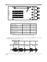
Page 129: ...C 10 Option 20A Four Fiber Optic Outputs 111 Figure C 7 Option 20A Jumper Locations ...

Page 130: ...ce impedance each channel will drive a 50 Ohm load to 3 Vpp minimum requires Option 92 in Model 1093A B C Unmodulated 5 V open circuit 4 V minimum at 250 mA load current each channel will drive 25 Schweitzer SEL 3xx in parallel or 50 SEL 2xx in series parallel relays at 10 mA per relay Maximum Load per driver Modulated No Limit will drive a short circuit Unmodulated 250 mA peak current pulse by pu...

Page 131: ...C 11 Option 27 8 Channel High Drive 113 Figure C 8 Option 27 Jumper Locations ...

Page 132: ...ce figures were obtained using the following types of Belden Wire cross referenced to corresponding part number AWG20 AWG18 AWG16 AWG14 AWG12 Shielded 8762 8760 8719 8720 8718 Non Shielded 8205 8461 8471 8473 8477 Table C 5 Example Output Load and Loop Distance Matrix 1 Output Load and Voltage Drop SEL 3xx is the number of relays connected as output load 2 For SEL 2xx using pairs of relays with in...

Page 133: ... or less Note 1 Shielding is optional However if shielding is used connect drain wire at source end of cable to a local surge ground Maintain shielding throughout bus by connecting drain wires together at each junction or drop point Do not connect drain wires at ends of cables Do not connect drain wires to signal wires Do not connect shield to ground at more than one location as this may result in...

Page 134: ...ng lines are short 5 ohms or less loop resistance then no further analysis is required As with unmodulated signals two or more drivers may be paralleled if desired Unlike the current limited unmodulated IRIG B drivers the modulated IRIG B drivers are impedance limited and will operate properly into any load impedance including a short circuit If the loop resistance is greater than 5 ohms then it m...

Page 135: ...nput to the Option 28 assembly using the 6 m 20 ft length of twin axial cable provided Strip the unterminated end of this cable and prepare it as required for termination to your System Reference signal Do not connect the shield of the cable at the reference input end 2 Attach this cable to the Option 28 System Reference input Hold the cable connector by its body not by the rotating locking ring a...

Page 136: ...VENT DEVIATION setup menu Press ENTER The following is displayed DISPLAY OPT 28 ONLY UP YES DOWN NO 5 To view Option 28 only press the UP key then press the front panel key EVENT DEVIA TION to display Option 28 measurement information 6 To enable Event Deviation A and B displays as well press the DOWN key and config ure the Channel Mode Time and Recorder Channel Then press the front panel key EVEN...

Page 137: ... is multiplied by the measured result to generate the displayed value If an accurate ac source at 50 or 60 Hz is available for example the Arbiter Systems Inc Model 1040C Panel Meter Calibrator the error for boards with prefix 97420 can be measured and the correction factor entered as described For example if 120 Vrms is applied to the Option 28 assembly and the display indicates 119 1 Vrms the ca...

Page 138: ...th frequency above nominal C 12 9 Option 28 Commands Return System Frequency Command FS FS returns Option 28 system frequency Response SS ff fffC Where SS UTC seconds ff fff frequency Hz Return System Frequency Deviation Command FD FD returns the system frequency deviation Response SS f fffC Where SS UTC seconds f fff frequency Hz Return System Phase Command PS PS returns the system phase Response...

Page 139: ...tatus Command SM SM returns the Option 28 system status Response hC Where h 0 System OK 1 No System Reference 2 System okay now but reference lost since last request Start Broadcast Mode Vorne Command B2 B2 configures RS 232 broadcast mode to support Vorne large format time displays Data is trans mitted ahead of time and the BEL character is transmitted on time When properly configured the Vorne d...

Page 140: ...ge values and leading blanks Decimal points are implicit and do not appear in the data stream Time Deviation Range Format b blank Below 999 99 bbb bbb 999 99 to 100 00 sss sss 99 99 to 10 00 bss sss 9 99 to 0 01 bbs sss 0 00 to 9 99 bbs sss 10 00 to 99 99 bss sss 100 00 to 999 99 sss sss Above 999 99 bbb bbb Table C 6 Option 28 B2 Broadcast Time Deviation Values Start Broadcast Mode ASCII Command ...

Page 141: ...lity and Frequency once per second in True Time format Response broadcast mode UTC SOH DDD HH MM SSQTsDS thmFsU thmC Where SOH ASCII start of header character 01h DDD Day ASCII colon 3Ah HH Two digits of the hour of day MM Two digits of the minute of day SS Two digits of the second of day Q Quality Sentry character space 20h error 5 1 µs period 2Eh 1 5 error 10 µs asterisk 2Ah 10 5 error 100 µs po...

Page 142: ...e Offset in degrees k Security Key e g 1093 Set Voltage Amplitude Correction Command v kRV v kRV sets the system voltage amplitude correction Response C Where v Voltage correction per unit with 1 000000 equal to no correction k Security Key e g 1093 Return Time Frequency Phase Deviation with UTC Time Command nPD nPD returns the System Time Frequency and Phase Deviation with a UTC time reference at...

Page 143: ...ssL Time of Day Local ss Status 0 Locked 1 Unlocked first character is Reference Status second character is clock status per IEEE P1344 f fff signed Frequency Error in Hz t tttt signed Time Deviation in seconds ppp pp Phase Angle 0 to 360 degrees vvv vv Line voltage rms Volts ...

Page 144: ...ctors provided The connec tors accept wire sizes of 0 25 to 2 5 mm2 AWG 12 to 22 See Table C 7 and Figure C 10 for Connector Configuration Digital Outputs Output Quantity 4 Output Type 5 V CMOS individually configurable Output Rating 5 V open circuit nominal 75 mA peak current per channel 3 5 V typical at 75 mA peak current Available Output Sig nals Jumper selectable to any of the digital signals ...

Page 145: ...r grounded load 4 25 50 VDC with contact closure to ground for non grounded load See Table C 13 2 Operating Modes of SSR Outputs Operating Modes of SSR Outputs Mode Dry Contact Closure 1 SSR Output 1 Connect load to pins 10 11 polarity not important 2 SSR Output 2 Connect load to pins 14 15 polarity not important Mode Contact Closure to Ground 1 Short pins 9 10 connect load to pin 11 2 Short pins ...

Page 146: ...PM 15 SSR Output 2 JMP8 Standard 50 ms Default 50ms 16 Leftmost 25 50 VDC 2 JMP11 25 50 VDC Default 50 VDC Table C 7 Output Connectors and Setup Jumpers C 13 3 Firmware Configuration 1 It is necessary to verify the configuration in the Option Setup Menu so Option 29 is recognized 2 Apply power and observe the front panel display when CLOCK STATUS STARTUP is displayed press the SETUP key 3 Navigate...

Page 147: ... from rear panel 2 Remove rack ears if equipped and remove top cover using a T 25 Torx driver 4 screws 3 Locate the appropriate Jumper using Figure C 9 and move the jumper to the desired setting 4 Replace the top cover and rack ears if equipped 5 Connect the power cord to the rear panel and set the Line Power switch to ON position if equipped Figure C 9 Option 29 Jumper Locations ...

Page 148: ...130 Options List Figure C 10 Option 29 Connector Signal Locations ...

Page 149: ...ic checksums If authentication is not used the controller can typically be used for hundreds of clients without overloading it Au thentication requires typically 40 ms for checking and generating the cryptograms which is covered and averaged out by the protocol Option 32 33 supports full SNTP and all NTP functions required for reliable server operation Functions not required for server operation a...

Page 150: ...wered on After the initial self test phase where all status LEDs should be lit the LED s indicate the status of the NTP Server Link LED Link green LED on Ethernet 10 100 base T connection is good Synch LED Synch green LED on synchronized to the time signal correct reception of time data requires the satellite controlled clock to be synchronized Synch LED flashing 50 duty cycle Some information rec...

Page 151: ... and following Rev A Board Modes JMP1 A Determined by Model 1088B same B Det by Model 1084A B C or 1093A B C same JMP2 A NTP Server s same B Clock serial port same C Configure NTP Server 1 via RS 232 only same D Configure NTP Server 2 via RS 232 only same JMP3 A NTP Server s same B Clock serial port same C Configure NTP Server 1 via RS 232 only same D Configure NTP Server 2 via RS 232 only same JM...

Page 152: ...ges Ethernet Initially NTP servers are programmed with the IP address of 192 168 0 232 To configure the NTP module over the network establish a Telnet connection to port 9999 If the IP address of the NTP Server NTS is unknown or undefined the following sets a temporary IP address a Set a static ARP with the desired IP address using the hardware address of the NTS which is printed on the product la...

Page 153: ...TPI IP addr 192 168 0 232 no gateway set Security SNMP is enabled SNTP Community Name public Telnet Setup is enabled TFTP Download is enabled Port 77FEh is enabled ECHO is enabled NTS parameters Antenna Type GPS Arbiter Encryption is disabled Sending UDP datagram to Port 024C hex every 000 minutes Send UDP datagram to Change Setup 0 Basic configuration 1 NTS configuration 6 Security 7 Factory defa...

Page 154: ... as the network section and how many bits are to be taken as the host section reminder Standard class A 8 24 net host class B 16 16 class C 24 8 bits If set to 0 the standard appropriate net mask for the actual IP address is used The NTS prompts for the number of host bits and then calculates the net mask It is shown in standard format 255 255 xxx xxx when parameters are displayed Telnet Config Pa...

Page 155: ...ation option is enabled up to seven MD5 or DES keys can be entered key numbers 1 7 All key input must be done in hexadecimal format MD5 key length is limited to eight characters When leaving the setup mode after selecting function 9 all parameters are stored in a nonvolatile memory and the NTP server resets Select 8 to exit without saving modifications ...

Page 156: ...on via DES and MD5 cryptographic checksums as defined in RFC 59053 Option 34 supports symmetric key au thentication Time is distributed over the network interface to computers controllers and other equipment needing the correct time Option 34 allows a secure connection to configure using either the preferred HTTPS Web Interface or using the SSH Console Precision Time Protocol PTP Server Option 34 ...

Page 157: ...ps power cycle the clock Default Port Addresses By default Option 34 comes configured as follows Port 1 IP address STATIC 192 168 0 232 Netmask 255 255 255 0 Gateway xxx xxx xxx xxx Port 2 IP address DHCP xxx xxx xxx xxx Selecting Option 34 in Clock Before you can use Option 34 in your clock make sure that it is selected as an option Selection may be checked at the front panel for Models 1084B C 1...

Page 158: ...ll return dashes for the IP address of that port The MAC address will still be returned as illustrated below NET1 192 168 000 232 64 73 E2 XX XX XX NET2 64 73 E2 XX XX XX NTP Status Display Indications GPS Clock and Server Stabilizing During the stabilization process the clock will display different status messages that indicate whether the NTP server is ready to serve time Clock stabilization req...

Page 159: ...NET1 192 168 000 232 64 73 E2 XX XX XX To Determine IP Address for 1093A 1084A For clocks without a display type IP at the terminal window as explained in Section C 15 2 and the clock should return the IP and MAC addresses for both ports in separate lines Option 34 LED Indications To view the Option 34 Status LEDs see the Option 34 rear panel The figure and Table C 10 below describe the indication...

Page 160: ...ss and use that one 3 Press the ENTER key which should open the web interface login as seen below Username Password Login 4 Type in the Username and Password The Username is clockoption and the default Password is password 5 Click the Login button If you typed in the correct Username and Password the web interface should appear as shown in Figure C 13 The IP Address By default Net1 Ethernet port i...

Page 161: ...et Time Quality NTP PTP SNMP SNMP Traps Temperature 01 May 2013 15 01 14 PDT 158 us Locked Running Enabled Running Enabled Running Enabled o 33 4 C Figure C 13 Startup Page System Configure Page Figure C 14 illustrates the System configuration page for Option 34 It includes configuring for HTTP or HTTPS see next section enabling session time outs for the web interface and console responding to pin...

Page 162: ...System Configure Page System Configure HTTPS Page To configure the HTTPS page follow these instructions Figure C 15 shows how configuring for HTTPS protocol opens up a dialog to upload a PEM file to the Option 34 system After opening the System Configuration page shown in Section C 15 3 click the HTTPS button and it will open the PEM file dialog shown in Figure C 15 Notice that the ports have chan...

Page 163: ...click the Choose File button shown in Figure C 17 This should open your file browser in which you should be able to locate the file package obtained from Arbiter Systems Click the Update button and the file should load to the Option 34 After uploading the package the Option 34 must be rebooted for the changes to take effect Upload Reset Upload Package File Choose File no file selected Figure C 17 ...

Page 164: ...tandard data traffic statistics Option 34 Network Time Module Status Configure NTP PTP SNMP Clock System Support Logout Network Ethernet Port 1 IP Address 10 10 1 59 MAC Address 64 73 E2 00 00 0B Bytes Packets Errors Dropped 746214455 9503596 20 34534 98631446 1026146 11 0 Rx Tx Ethernet Port 1 IP Address 192 168 0 65 MAC Address 64 73 E2 00 00 0C Bytes Packets Errors Dropped 0 0 0 0 1692476 24730...

Page 165: ...TP PTP SNMP Clock System Support Logout Network Ethernet Port 1 MAC Address 64 73 E2 00 00 0B Mode DHCP Static Enable VLAN Ethernet Port 2 MAC Address 64 73 E2 00 00 0C Mode DHCP Static Address Netmask Gateway Enable VLAN Apply Reset 192 168 0 65 255 255 255 0 Figure C 20 Configure Network Settings Configure VLAN To configure VLAN network settings follow these instructions Check the box to the lef...

Page 166: ...02 May 2013 14 18 03 PDT Time Quality Satellites Tracked Satellites Visible Leap Seconds Current GPS UTC Offset Status Locked 10 10 16 Not Pending Figure C 22 View Operation SNMP Status View this web interface page to check the SNMP status as illustrated in Figure C 23 For additional detail on SNMP in the Model 1093A B C see SNMP Support in Section C 15 5 Option 34 Network Time Module Status Confi...

Page 167: ... System Time Set System Time Change Zero Satellites Visible NTP Application Start NTP Application Stop PTP Application Start PTP Application Stop SNMP Application Start SNMP Application Stop Trap Receivers IP Address 1 IP Address 2 IP Address 3 10 10 1 236 Apply Reset Figure C 24 SNMP Configuration Page Checking the box enables the specific item unchecking disables the specific item in the SNMP Co...

Page 168: ...nd the Status tab above 35 is the Current UTC PTP Offset in seconds Figure C 25 illustrates the status of PTP Option 34 Network Time Module Status Configure NTP SNMP Clock Network System Support Logout PTP PTP Service Current UTC PTP Offset Enabled Running 35 Figure C 25 PTP Status Page ...

Page 169: ... Hide Advanced seconds seconds seconds seconds Figure C 26 PTP Configuration Page PTP Terms Domain a collection of one or more PTP subdomains A subdomain is a logical grouping of 1588 clocks that synchronize to each other using the PTP protocol but that are not necessarily synchronized to PTP clocks in another PTP subdomain Subdomains provide a way of implementing disjoint sets of clocks sharing a...

Page 170: ... NTP Status Page To view the NTP service select NTP tab on the left and the Status tab above Figure C 27 illustrates the status of NTP Option 34 Network Time Module Status Configure NTP PTP SNMP Clock Network System Support Logout Authentication NTP Root Dispersion Offset Frequency System Jitter Clock Jitter Clock wander Stratum Running 0 420 0 063 1 337 0 009 0 008 0 001 1 Figure C 27 NTP Status ...

Page 171: ...atum the level of each server in the hierarchy is defined by a stratum number Primary servers are assigned stratum one NTP Configure To configure NTP follow these instructions Figure C 28 illustrates the NTP configuration page Choices for the NTP Version include Versions 1 2 3 and 4 Multicast and Broadcast addresses may be typed in the assigned boxes Option 34 Network Time Module Status Configure ...

Page 172: ...revents them from updating the local clock NTP authentication is disabled by default Option 34 Network Time Module Status Configure NTP PTP SNMP Clock Network System Support Logout Authentication Apply Reset M Enable Authentication M M M M Key Table ID Format Key Trusted Figure C 29 NTP Authentication Page There are four authentication formats S N A M with different rules for each of the keys For ...

Page 173: ...es CA 93446 805 237 3831 800 321 3831 US Canada Mexico only Mon Thu 7 00am 5 30pm Pacific Time www arbiter com techsupport arbiter com Option 34 Network Time Module Contact Version NTP PTP SNMP Clock Network System Support Logout Web Management Core Modules Option 34 35 Auth01 Option 34 35 Data Server Firmware Hardware Option 34 Startup App System Monitor CLOI Arbiter 1093 Board 01 462 1 4 1 4 1 4...

Page 174: ...s provides an overview of the operation of the Option 34 NTP PTP servers Figure C 31 illustrates the opening page Status Configure Password Update Reboot System Time 11 24 17 04 19 2011 System Time Offset 114us Time Quality Locked NTP Running PTP Enabled Running SNMP Enabled Running SNMP Traps Enabled Temperature 33 3C ARBITER SYSTEMS Option 34 Network Time Module NTP PTP SNMP Clock Network System...

Page 175: ...ting your time zone Time zone setting only changes the time as it is read on the clock display Just as the receiving device must convert the NTP PTP time as it arrives at the device to local time zone so the clock can display local time Status Configure Password Update Reboot Web Interface HTTP HTTPS Port 443 PEM File Download Replace Enable Session Timeout Console Interface Enable Session Timeout...

Page 176: ...eep it in a safe place Status Configure Password Update Reboot Current Password New Password Confirm New Password Apply Reset ARBITER SYSTEMS Option 34 Network Time Module NTP PTP SNMP Clock Network System Support Logout Computer Name or IP address ssh 80x24 Figure C 33 Configure System Password Using SSH System Update Use the Web Interface to perform any update For more information see Section C ...

Page 177: ...s MAC addresses and some standard data traffic statistics Status Configure Ethernet Port 1 IP Address 10 10 1 184 Hardware Address 64 73 E2 00 17 38 Bytes Packets Errors Dropped Rx 2649123 39782 0 110 Tx 1554398 11894 5 0 Ethernet Port 2 Not Active IP Address Hardware Address 64 73 E2 00 17 39 Bytes Packets Errors Dropped Rx 0 0 0 0 Tx 0 0 0 0 ARBITER SYSTEMS Option 34 Network Time Module NTP PTP ...

Page 178: ...17 38 DHCP Static Enable VLAN Ethernet Port 2 Hardware Address 64 73 E2 00 17 39 DHCP Static IP Address 10 10 1 185 Netmask 255 255 0 0 Gateway X Enable VLAN VLAN ID 123 VLAN Priority 2 Apply Reset ARBITER SYSTEMS Option 34 Network Time Module NTP PTP SNMP Clock Network System Support Logout Computer Name or IP address ssh 80x24 Figure C 35 Configure Network Settings Using SSH Enable VLAN From Fig...

Page 179: ...ime Quality Locked Satellites Tracked 10 Satellites Visible 10 Leap Seconds Current GPS UTC Offset 16 Status Not pending Figure C 36 View Operation Using SSH SNMP Status Use the cursor keys to select SNMP then Status and press ENTER to view the SNMP status as illustrated in Figure C 37 Status Configure SNMP Service Enabled Running SNMP Traps Enabled ARBITER SYSTEMS Option 34 Network Time Module NT...

Page 180: ...s Page Using SSH Configure PTP Service Please use the Web Interface to configure PTP See Section C 15 3 for more information NTP Status Page Use the cursor keys to select NTP then Status and press ENTER Figure C 39 illustrates the status page for NTP Status Configure NTP Enabled Running Root Dispersion 0 451 Offset 0 095 Frequency 8 623 System Jitter 0 008 Click Jitter 0 010 Clock Wander 0 001 Str...

Page 181: ...offset of the clock Clock wander is the RMS of exponentially weighted frequency differences This is not used directly but can along with the jitter be a highly useful monitoring and debugging tool Stratum the level of each server in the hierarchy is defined by a stratum number Primary servers are assigned stratum one NTP Configure To configure NTP follow these instructions Use the cursor keys to s...

Page 182: ...cal clock NTP authentication is disabled by default Status Configure Authentication X Enable Authentication Key Table ID Format Key Trusted M Apply Reset M M M M ARBITER SYSTEMS Option 34 Network Time Module NTP PTP SNMP Clock Network System Support Logout Computer Name or IP address ssh 80x24 Figure C 41 NTP Authentication Page Using SSH There are four authentication formats S N A M with differen...

Page 183: ...EMS Option 34 Network Time Module NTP PTP SNMP Clock Network System Support Logout Computer Name or IP address ssh 80x24 Contact Version Console UI Core 1 4 Modules Option 34 35 1 4 Auth01 1 4 Option 34 35 Data Server 1 4 Firmware Hardware Option 34 2 1 Startup App 1 1 System Monitor 1 1 CLOI 1 2 Arbiter 1084 07 May 2013 Board 01 462 01 e 1244012 ARBITER SYSTEMS Option 34 Network Time Module NTP P...

Page 184: ...he NMS to set the values of the object instances within an agent TrapUsed by agents to asynchronously inform the NMS of a significant event SNMP v2 Additional Operations and Features GetBulkUsed by the NMS to efficiently retrieve large blocks of data InformAllows one NMS to send trap information to another NMS and to then receive a response SNMP v3 Security Enhancement User based Security Model US...

Page 185: ...raps At the bottom are three boxes for IP addresses designated as trap receivers where trap messages may be sent SNMP Configuration Reference Listed below are the configurable options available for snmp traps Trap events will only be sent out if the Trap Receivers are selected and identified by a valid IP address Enable SNMP Service Select this item to make the snmp service active Enable SNMP Trap...

Page 186: ...SNMP agent that runs on Option 34 is also available for download and use in the Model 1093A B C The MIB table is normally loaded in a MIB browser and the agent is normally uploaded into the Option 34 ARBITER ALL MIB Revision 0 0003 3 DEC 2012 ARBITER ALL MIB DEFINITIONS BEGIN IMPORTS MODULE IDENTITY OBJECT TYPE enterprises Integer32 Unsigned32 FROM SNMPv2 SMI TEXTUAL CONVENTION TruthValue FROM SNM...

Page 187: ...TP server arbiter 3 ntpsys OBJECT IDENTIFIER ntp 1 ntptrap OBJECT IDENTIFIER ntp 2 Textual Conventions MilliUnits TEXTUAL CONVENTION DISPLAY HINT d 3 STATUS current DESCRIPTION SYNTAX INTEGER MicroUnits TEXTUAL CONVENTION DISPLAY HINT d 6 STATUS current DESCRIPTION SYNTAX INTEGER General Device Information sysDevLabel OBJECT TYPE SYNTAX OCTET STRING MAX ACCESS read only STATUS current DESCRIPTION ...

Page 188: ...rent DESCRIPTION The device model device 4 version OBJECT IDENTIFIER device 5 sysDevVerLabel OBJECT TYPE SYNTAX OCTET STRING MAX ACCESS read only STATUS current DESCRIPTION The device model version 1 sysDevVerCore OBJECT TYPE SYNTAX OCTET STRING MAX ACCESS read only STATUS current DESCRIPTION The device model version 2 sysDevVerMonitor OBJECT TYPE SYNTAX OCTET STRING MAX ACCESS read only STATUS cu...

Page 189: ... 6 sysDevVerPTP OBJECT TYPE SYNTAX OCTET STRING MAX ACCESS read only STATUS current DESCRIPTION The device model version 7 sysDevVerSNMP OBJECT TYPE SYNTAX OCTET STRING MAX ACCESS read only STATUS current DESCRIPTION The device model version 8 sysDevClockModel OBJECT TYPE SYNTAX OCTET STRING MAX ACCESS read only STATUS current DESCRIPTION The device model device 6 sysDiagLabel OBJECT TYPE SYNTAX O...

Page 190: ...ION The operational status of NTP diag 4 rec1 OBJECT IDENTIFIER gnss 1 gnssRec1Label OBJECT TYPE SYNTAX OCTET STRING MAX ACCESS read only STATUS current DESCRIPTION String identifier for receiver 1 rec1 1 gnssRec1Type OBJECT TYPE SYNTAX OCTET STRING MAX ACCESS read only STATUS current DESCRIPTION Receiver 1 GNSS system type rec1 2 gnssRec1SatsVisible OBJECT TYPE SYNTAX Integer32 MAX ACCESS read on...

Page 191: ...m shutting down systrap 2 systrapAdminLogin OBJECT TYPE SYNTAX OCTET STRING MAX ACCESS accessible for notify STATUS current DESCRIPTION System administrative login systrap 3 systrapAdminLogout OBJECT TYPE SYNTAX OCTET STRING MAX ACCESS accessible for notify STATUS current DESCRIPTION System administrative logout systrap 4 systrapTimeQuality OBJECT TYPE SYNTAX INTEGER32 MAX ACCESS accessible for no...

Page 192: ...AX ACCESS read only STATUS current DESCRIPTION the current local time Local time is derived from the hardware clock of the particular machine and increments at intervals depending on the design used ntpsys 3 ntpSysOffset OBJECT TYPE SYNTAX Integer32 MAX ACCESS read only STATUS current DESCRIPTION ntpsys 4 ntpSysFreq OBJECT TYPE SYNTAX MilliUnits MAX ACCESS read only STATUS current DESCRIPTION ntps...

Page 193: ...ad only STATUS current DESCRIPTION the maximum error relative to the primary reference source at the root of the synchronization subnet in seconds Only positive values greater than zero are possible ntpsys 10 ntpSysLeap OBJECT TYPE SYNTAX Integer32 MAX ACCESS read only STATUS current DESCRIPTION two bit code warning of an impending leap second to be inserted in the NTP timescale ntpsys 11 ntpSysSt...

Page 194: ...ized the value is zero ntpsys 14 ntptrapPowerUp OBJECT TYPE SYNTAX OCTET STRING MAX ACCESS accessible for notify STATUS current DESCRIPTION NTP server powering up ntptrap 1 ntptrapShutDown OBJECT TYPE SYNTAX OCTET STRING MAX ACCESS accessible for notify STATUS current DESCRIPTION NTP server shutting down ntptrap 2 ntptrapSynchronized OBJECT TYPE SYNTAX OCTET STRING MAX ACCESS accessible for notify...

Page 195: ...ed ASCII string In the case of stratum 2 and greater secondary reference this is the four octet Internet address of the peer selected for synchronization ntpSysRefTime the local time when the local clock was last updated If the local clock as never been synchronized the value is zero ntpSysPoll the minimum interval between transmitted messages in seconds as a power of two For instance a value of s...

Page 196: ... Two Ethernet Version 2 0 IEEE 802 3 10 100BT or multimode SSF modules Protocols NTP SNTP PTP IEEE 1588TM 2008 UDP ICMP SNMP TCP SSH SCP SSL HTTP HTTPS Operator Interface Management Web and SSH Console Status LEDs Sync green Fault red Link green 10baseT yellow 100baseT Setup IP number DHCP or Static Net Mask Reference Identifier UDP Broadcast parameters MD5 and DES authentication keys are optional...

Page 197: ...y might look like the following BEGIN RSA PRIVATE KEY MIICXgIBAAKBgQDPoNigXmq2JAlw9DrD0P5Og5c5xsEnt9bPjfuE7MGkDEGN09sC more data 8Xxzzgu4xizBdLmONkHu7b h7GL6u5smkWVOCesCCR0mKw END RSA PRIVATE KEY Step 2 Generate a Certificate Signing Request CSR The following command will generate a CSR certificate signing request file using the private key generated in Step 1 OpenSSL will prompt for several piece...

Page 198: ...ire contents of the file including the BEGIN and END tags with the dashes into the vendor s web form Once the purchase has been completed and other verification steps completed this will vary from vendor to vendor they will provide you with a certificate file You may skip to Step 4 Step 3B Generate a Self Signed Certificate If you do not need a commercially purchased certificate the following comm...

Page 199: ...ralian Standard CAS 9 30CAD Eastern Standard Brazil EST3EDT Japan Standard Time JST 9 Greenland Standard Time GST3 Korean Standard Time KST 9KDT Newfoundland Standard Time NST3 30NDT China Coast Time CCT 8 Atlantic Standard Time AST4ADT Hong Kong Time HKT 8 Western Standard Brazil WST4WDT Singapore Standard Time SST 8 Eastern Standard Time EST5EDT Western Australian Standard WAS 8WAD Chile Standar...

Page 200: ...gnal characteristics IRIG B time code modulated onto 1 kHz 4 5 Vpp sine wave carrier Digital Outputs Output Type High Speed CMOS 74HC126 0 to 5 volts with 47 ohm series resistance Available Outputs Unmodulated IRIG B 1 PPS Programmable Pulse Out of Lock IRIG B IRIG format B time code unmodulated C 16 3 Changing Outputs via Internal Settings Case Removal To change the configuration of Option 36 the...

Page 201: ... to provide unmodulated IRIG B place each function jumper to position 3 Mode Selection Jumpers JMP9 JMP10 JMP11 JMP12 control the signal driver for each output analog or digital Make sure to select these output mode jumpers for each output For each output position A selects a digital driver and position B selects an analog driver The table below indicates the correct jumper for each output Desired...

Page 202: ...ion 36 Jumper Configuration Output Signal Function Jumper Mode Jumper IRIG B Modulated 1 B IRIG B Unmodulated 3 A 1 PPS 18 A Programmable Pulse 19 A Out of Lock 20 A Table C 11 Option 36 Output Connector Jumper Settings If IRIG B is chosen as the output signal then each selected output should produce a waveform very similar to the drawings in the figure below ON TIME 1 PPS IRIG B003 B004 REFERENCE...

Page 203: ...modulated IRIG B distribution bus which provides a low impedance fault protection output 4 Vpp 20 Ohm source impedance A second EPROM adds IRIG B modulation and is mounted on the main board Option 92 is field installable C 19 Option 93 Out of Lock Relay Model 1092A B C and Model 1093A B C Option 93 adds a single form C single pole double throw SPDT relay activated by the out of lock signal This is...

Page 204: ...trip outputs while the fourth connector provides a BNC event deviation input The standard pluggable terminal strip outputs are still usable but both connectors now share the drive capability Physical Configuration The connectors are mounted on an option plate connected to the rear panel with four M3 Kepnuts and connected to the main board with a five pin connector J3 The signals on the output are ...

Page 205: ...g style strip connector For programmable pulse information see Section 7 8 the Setup Menus and 10 2 12 Programmable Pulse Output Commands C 24 Option 98 Event Input Model 1092A B C and Model 1093A B C Event input is converted from the standard IRIG B modulated output Configuration allows 5 VDC TTL level inputs to be timed and recorded based on the GPS clock time For background information and setu...

Page 206: ...dix D CE Mark Certification D 1 Introduction On the following pages contain the individual CE Mark Certifications for models covered in this manual This includes Model 1092A 1092B 1092C 1093A 1093B and 1093C ...

Page 207: ... Robles CA 93446 USA Harmonized EN55011 Class A Radiated and Conducted Emissions Standard EN50082 1 Generic Immunity Part 1 Referenced Residential Commercial and Light Industrial Environments EN61010 1 Safety requirements of Electrical Equipment for Measurement Control and Laboratory Use Signed Signatory Bruce H Roeder This certificate declares that the described equipment conforms to the applicab...

Page 208: ...Appendix E Statement of Compliance E 1 Introduction The following page is a statement of compliance that includes Model 1092A 1092B 1092C 1093A 1093B and 1093C ...

Page 209: ...oducts are available with all known time synchronization signals presently in use world wide by the electric power industry Arbiter Systems does not supply a type test certificate as requested for G P S systems as the accuracy is a function of the G P S system and not of the receiver However we Arbiter hereby certify that this equipment conforms to all Arbiter Systems Incorporated specifications f...

Page 210: ...9 effects of cable parameters 19 Appendix A 91 B 97 C 99 D 155 E 163 battery data backup 26 cable accessory 20 adjacent signal interference 21 delays 58 distance 56 physical protection 20 timing output 56 user supplied 21 wire losses 57 CE mark certifications 155 chapter list v command key definitions 6 communication ports 65 configure begin 33 settings auto survey 48 back light 40 broadcast 36 da...

Page 211: ...ock time 28 initial LED indication 27 initial startup sequence 27 inlet power 11 IRIG B IEEE 1344 description 54 initial indication 30 modulated voltage matching 58 timecode description 53 54 unmodulated 54 waveform comparison 54 year information 54 issuance ii jumpers function selection 25 JMP1 output signal select 23 JMP2 output signal select 23 JMP3 output signal type 23 JMP4 output signal type...

Page 212: ...ctors 153 Option 96 Prog Pulse Output 153 Option 97 IRIG B reconfig to Prog Pulse 154 Option 98 Event Input 154 options list 99 output signal description 52 panels drawing front 6 rear 8 51 front 5 rear 5 position display modes 32 datum 32 Position Hold commands 84 power supply voltage 18 programmable pulse description 55 pulse width 55 with 200 Volt FET 55 rack mount ears mounting instructions 2 ...

Page 213: ...olarity 87 set pulse width 86 set time mark 86 Pulse Per Hour 86 Return IP MAC address 89 return display buffer 88 elevation 83 firmware version 88 latitude 83 local date 85 local time 85 longitude 83 Seconds per Pulse 86 Set deviation operation 76 77 Set event operation 76 set IEEE 1344 mode 82 set local time 82 set receiver time 85 set UTC time 82 Status clock 78 EEPROM 78 receiver 78 status of ...

Page 214: ...port request iii synchronizing multiple devices on one port 56 time display modes 31 timing outputs description 51 intro 51 title page v True Time broadcast mode 125 unpacking the clock 1 version firmware 88 manual v warranty iii wire losses 57 ...

Reviews: