
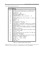
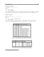

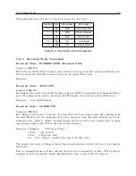
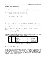
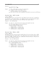
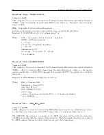

8.4 Connecting the Outputs
57
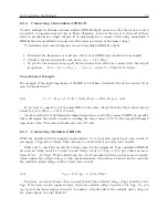
Since electromagnetic waves travel slower through any cable, cable manufacturers normally
specify cable with a velocity factor (VF), which is a percentage of the speed of light in free space,
and characteristic of the specific cable. The Velocity Factor for the RG-6 cabling used by Arbiter
Systems for GPS antenna connections, is about 83% of C. Most transmission lines have velocity
factors in the range of 65% to 97%. Using these values you can determine the actual time delay in
your cable distribution system and compare it to your required accuracy. As an example, 840 feet
of RG-6 cable (with a velocity factor of 83%) would delay the timing signal by one microsecond.
For IRIG-B timing applications, these delays may not be important, compared to other criteria.
Otherwise, you would be forced to compensate for the time delay using another method, such as
advancing the timing output or placing another master clock at the remote site.
8.4.9
Solutions
There are many solutions to providing an accurate timing signal to equipment in distant locations.
However, the most satisfying solution may not be to string cabling for hundreds of meters. The
costs associated with installing and maintaining cabling over a wide area may be unsatisfactory.
Since the GPS is so pervasive, it may prove to be less costly to install another clock at a distant
location, which would also improve accuracy and provide redundancy. Before installing cabling
over a wide area, be sure to first examine all the possibilities.
Summary of Contents for 1092A
Page 4: ...iv ...
Page 18: ...xviii LIST OF TABLES ...
Page 129: ...C 10 Option 20A Four Fiber Optic Outputs 111 Figure C 7 Option 20A Jumper Locations ...
Page 131: ...C 11 Option 27 8 Channel High Drive 113 Figure C 8 Option 27 Jumper Locations ...
Page 148: ...130 Options List Figure C 10 Option 29 Connector Signal Locations ...


