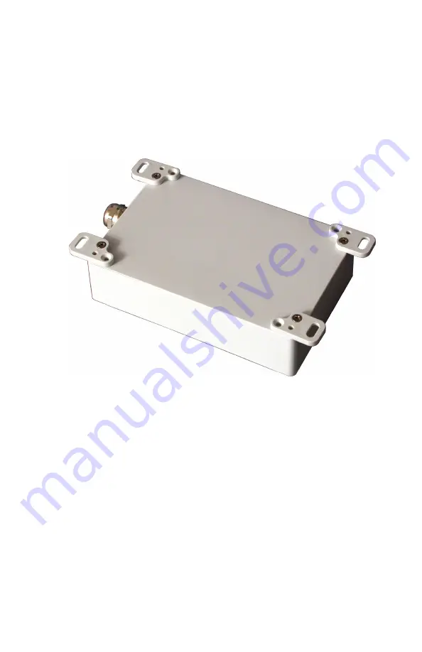
1. Drop the hex nut into the opening next to the cover-mounting
screw and hold in place with a pencil or dowel.
2. Align the tab with the hole, in the desired orientation, and mount
the M3 screw through the tab and into the rear panel mounting
hole as shown in Figure 2.1.
3. Tighten the four screws.
Figure 2.1: Model 1095A/C Mounting Tabs, Attached
2.7
Connecting Input & Output Wiring
This section will assist you with connecting all input and output signals
to the Model 1095A/C clocks. All standard input and output signals are
routed through the sealing cable port at the bottom of the clock housing;
this includes inlet power.
2.7.1
Internal Antenna Operation
No antenna wiring is required when equipped with an internal GPS
antenna.
For GPS reception using the internal antenna, the Model
11


