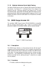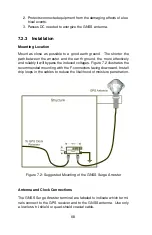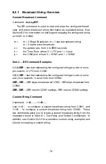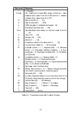
length and/or type of antenna cable should be made carefully. Damaged
cables may also affect performance.
7.1.3
Cable Delay
The velocity factor and the physical length of the cable determine cable
delay. During the initial factory calibration of the clock, a value for cable
delay (based upon the length and type of cable supplied) is entered into
the clock memory. Firmware uses this figure to counteract the effect
that the delay has upon GPS timing. The value entered for a standard
6-meter cable is 24 nanoseconds. For other cable options, the delay is
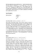
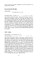
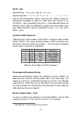
tabulated in Table 7.1. To calculate cable delay, see Equation 7.1:
(7.1)
T
=
λ
1
CKv
+ 1
ns
Where:
T = Cable delay, in nanoseconds;
λ
= Cable length, in meters;
C = Speed of light (
3
×
10
8
meters per second);
Kv = Nominal velocity of propagation (0.85).
One nanosecond is added to the calculated value to account for the
length of the short connecting cable inside of the clock.
7.1.4
Attenuation
Attenuation depends upon the cable length, and the loss per unit
length. The total attenuation must be limited to 21 dB (maximum) at
the GPS L1 frequency of 1575.42 MHz. Loss up to 42 dB can be
accommodated with the separately available 21-dB in-line preamplifier
(P/N AS0044700).
7.1.5
DC Resistance
The cross-sectional area and length of the conductors in the cable
determine the dc resistance. Since power to the RF preamplifier in the
antenna is supplied via the antenna cable, excessive dc resistance will
degrade performance.
64


