3.2
Using an External Antenna
When planning to mount the Model 1095A/C indoors, order the Option
01, External GNSS Antenna. With this option, the Model 1095A/C will
be equipped with a Type-F antenna connector next to the sealing cable
port. Mount the external antenna with a clear view of the sky at all points
of the compass. Partial views impose the same limitations as reviewed
in Section 3.1.2 with the internal antenna.
3.2.1
External GNSS Antenna, Option 01
If you purchase the Option 01, External GNSS Antenna, with the Model
1095A/C it will include three components.
• GNSS Antenna
• RG-6 antenna cable assembly (6 meters)
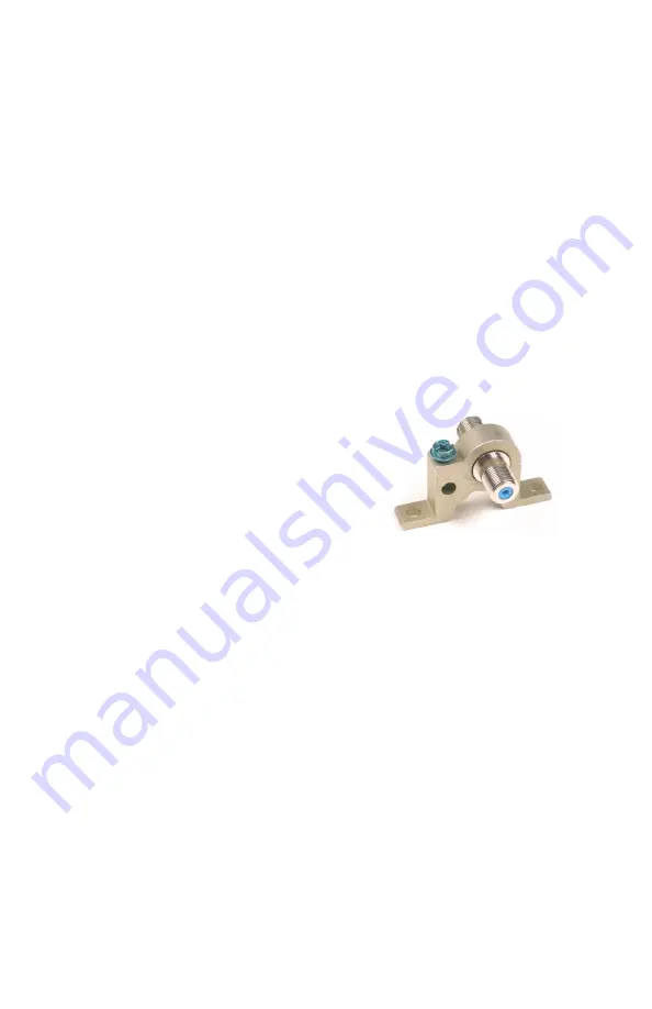
• Grounding block, includes 2 male F connectors
Figure 3.2: Grounding Block
3.2.2
Using the Grounding Block
Bolt the grounding block to an earth ground, or ground using a short
length of 8 – 14 AWG wire between the grounding block and earth
ground. Connect the antenna cable between the GNSS antenna and
the grounding block. Also included with the Grounding Block Kit are
two RG-6 connectors for splicing in the grounding block. Alternately,
fabricate an RG-6 cable to connect between the grounding block and
the Model 1095A/C with external antenna connector. Use a suitable
crimp tool to mount the connectors to the cable – cable, connectors and
crimp tool are available from the factory.
3.2.3
Technical Details on External Antennas
Chapter 7 covers more information on using an external antenna with
the Model 1095A/C. This includes (1) length and loss considerations,
19


