


Chapter 10
Relay Contacts and Event Inputs
10.1
Relay Contacts
10.1.1
Introduction
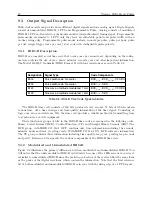
Model 1201B/C provides a single set of mechanical SPDT relay contacts, which typically have a lifetime of
less than 100,000 cycles
. These contacts may be configured to indicate several clock conditions, or it may
be configured for a programmable pulse. If configured for programmable pulse, make sure to consider the
pulse frequency. For example, if configured for 1 PPS, the contacts could be used up in a less than two days,
depending on power dissipation. See also Section 2.3.6.
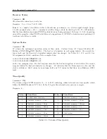
Specification
Value
Arrangement
1 set of Form C (SPDT) contacts
Contact resistance
100 mΩ
Operate, release time
Approx. 6 ms, 3 ms
Rated switching current
(resistive)
8 A at 250 Vac, 5 A at 30 Vdc
Max switching capacity
2,000 VA, 150 W
Expected life
50,000 electrical cycles (100,000 typical)
Min. permissible load
10 mA, 5 Vdc
Table 10.1: Relay Specifications
10.1.2
Relay Operation
Several clock conditions may be configured to trigger the Model 1201B/C relay. These include: (1) an
out-of-lock condition with the GNSS, (2) a fault, (3) an alarm
, (4) when the clock is not stabilized, and (5)
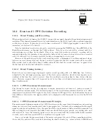
failsafe, which occurs with loss of inlet power. Figure 10.1 illustrates from the rear panel how the contacts
operate. A fault connects the normally closed contact (on the left) to the common contact (on the right).
The normally open contact (in the middle) operates in a manner opposite to the normally closed contact.
“Failsafe” defines the faulted condition that occurs when the clock is powered off.
1
Depends on applied voltage and current.
2
See page 29 for definitions on faults and alarms.
Summary of Contents for 1201B
Page 4: ...iv ...
Page 153: ...B 7 Four Fiber Optic Outputs 135 Figure B 4 Jumper Locations ...


