


2.3 Rear Panel Identification and Connectors
9
2.3.3
Optional Fiber Optic Output
An optional, single fiber optic output may be ordered and will source any available digital signal
in the Model 1201B/C. The port includes an ST connector and drives multimode fiber.
2.3.4
Event Input
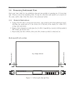
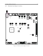
For timing external events based on the GNSS-synchronized time, you may use ports 1, 2, and 3,
COM1 (RS-232 port), and one of the optional BNC connectors. Figure 5.1 illustrates the locations
of these connectors and the internal jumpers.
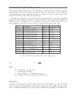
2.3.5
RS-232 and RS-485 Communication Ports
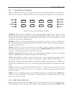
The Model 1201B/C has two standard communication ports–COM1 and COM2–with RS-232 sup-
ported on COM1 and COM2 and RS-485 supported only on COM1. Neither RS-232 port uses flow
control, and RS-485 is transmit only. RS-485 on COM1 provides for transmit A and transmit B,
but no receive A and receive B.
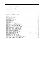
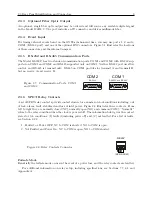
Figure 2.7: Communication Ports, COM1
and COM2
RS-232C and RS-485
COM 1
RS-232C
COM 2
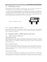
2.3.6
SPDT Relay Contacts
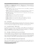
A set of SPDT relay contacts provide contact closure for a number of clock conditions including: out
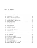
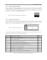
of lock, alarm, fault, stabilized and loss of inlet power. Figure 2.8 illustrates three contacts. From
left to right they are normally closed (NC), normally open (NO) and common (COM). “Normally”
refers to the relay condition when the clock is powered off. The information below gives the contact
states for two conditions: (1) faulted (including power off) and, (2) not faulted. For a list of faults,
see Section 6.2.2.
1. Faulted, or Power OFF: NC to COM is shorted, NO to COM is open.
2. Not Faulted and Power On: NC to COM is open, NO to COM shorted.
Figure 2.8: Relay Contacts Connector
RELAY
(NC NO COM)
Failsafe Mode
Essentially the failsafe mode occurs in the event of a power loss, and the relay contacts are faulted.
For additional information on relay setup, including specifications, see Sections 7.7, 8.4 and
Appendix A.
Summary of Contents for 1201B
Page 4: ...iv ...
Page 153: ...B 7 Four Fiber Optic Outputs 135 Figure B 4 Jumper Locations ...


